the12volt.com spacer
icon

constant to momentary


Post ReplyPost New Topic
< Prev Topic Next Topic >
e30vert 
Member - Posts: 5
Member spacespace
Joined: November 29, 2007
Location: California, United States
Posted: November 29, 2007 at 10:57 PM / IP Logged  

Hello All, 

I have read the posts concerning the Constant to Momentary Circuit and believe that it will help with the final circuit that I need to build.

Here is what I need to do.  Connect two wires (short them) for a small duration as if someone pressed a button for a moment.

Essentially I have a home automation system and would like to use an existing Applainace Control Module to simulate someone pressing my interior button of the garage door opener.

The Applicance Module will respond to commands and provide a constant 120 Volt AC output and then respond to another command to remove the 120 V AC output.

I have gone this far.

Hooked up a standard (cell phone charger transformer) ( 120 V AC to 9 Volts DC ) to the Applicance module. So when the appliance module is on and supplying 120 V AC I get 9 Volts DC over the two wires that come off of the transformer.  Ran the 2 wires from the transformer to a standard SPST Relay on pins 85 and 86. This DOES latch the relay and the coil is energised as long as there is power supplied. This creates a connection ( continuity) between pins 30 and 87.  I could connect the 2 wires from the garage door button to these pins , but that would just simulate the button being pressed indefinately.  I need the connection to drop away after a second or so.

Then it would be great if then when the applicance module turns off and removes the 120v AC->9 volt DC source voltage then the contacts are shorted or closed again briefly.

This would allow me to press once on the home automation controller and supply 120 V AC- >9 V DC and short the connection thus opening the garage door and then press again and remove the 120 V AC -> 9 V DC souce Voltage and then short the connection again thus closing the garage door. And over and over... :)

I really cant visulaize how to do the entire circuit so I thought I would post up and let HoTWater Wizard and others a chance to conquer this one!

Thanks mucho!

i am an idiot 
Platinum - Posts: 13,674
Platinum spaceThis member consistently provides reliable informationspace
Joined: September 21, 2006
Location: Louisiana, United States
Posted: November 30, 2007 at 6:51 AM / IP Logged  
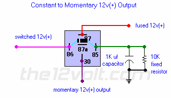
constant to momentary -- posted image. Constant to Momentary Output
The capacitor allows the coil of the relay to be energized until the capacitor stores a charge, thus de-energizing the coil. The resistor bleeds off the charge of the capacitor when positive voltage is removed from the other side of the coil. You can increase the output time by simply changing the value of the capacitor. This one will give you about a 1/2 second output.
 
constant to momentary -- posted image.
 
For all kinds of other neat relay projects look here   https://www.the12volt.com/relays/page5.asp
e30vert 
Member - Posts: 5
Member spacespace
Joined: November 29, 2007
Location: California, United States
Posted: November 30, 2007 at 1:43 PM / IP Logged  
Yes, I have that diagram and understand the concept. I dont need to have a 12 volt momentary output. I just need contact between two points that I can toggle back and forth. This has not answered my question entirely.
i am an idiot 
Platinum - Posts: 13,674
Platinum spaceThis member consistently provides reliable informationspace
Joined: September 21, 2006
Location: Louisiana, United States
Posted: November 30, 2007 at 9:25 PM / IP Logged  
The only thing that comes to mind is to Connect the 12Volt momentary out to 86 of another relay.  Ground pin 85 of the second relay.   Then 30 and 87 can be your 2 contacts that you are looking for.   I know you will have to activate your controller once to go up.  Then unactivate then reactivate to get it to go down.
e30vert 
Member - Posts: 5
Member spacespace
Joined: November 29, 2007
Location: California, United States
Posted: December 01, 2007 at 1:13 AM / IP Logged  
Sounds like it will work in theory. Too bad there is not an easy way to change from one state to the other without having to turn the appliance module on and then off and then  on again. Oh and then off.  They have a device that will operate low voltage contacts that is solid state circuitry, but they want about 150 $ for it!  When this solution can be cobled together for much much much less.  Thanks for the input and if you can think of a way to get it to truly toggle - one press for open and one press for close please post up. 
dualsport 
Silver - Posts: 983
Silver spacespace
Joined: September 27, 2005
Location: United States
Posted: December 01, 2007 at 9:42 AM / IP Logged  
A couple of logic gates can be used to output a momentary pulse when your input changes state, and that can be used to drive your relay for the momentary contact .
If you're using it for a GDO, you might have to make sure it wouldn't be a problem if you briefly lose power to your appliance module, and cause it to turn off, leaving your garage wide open when it causes a trigger.
The appliance modules aren't coded like regular garage door openers, so it might be prone to false activation- if security isn't a big concern then you could use it.
You might consider just getting an inexpensive RKE module and using that for controlling it; the remotes are probably a nicer size to carry around than those home automation remotes.
e30vert 
Member - Posts: 5
Member spacespace
Joined: November 29, 2007
Location: California, United States
Posted: December 01, 2007 at 2:31 PM / IP Logged  

Good suggestions.  Since the applicance module works off of the house's 110 V supply and the signal to turn off or on is sent through the line then yes it may be prone to spikes and such that could cause funky operation. 

I can build the simple circuit and try it out to see how it actually performs. If it is glitchy then I can substitute another solution.

Since I have a push button panel on the kitchen wall that would interface with the existing light control modules already installed and now the new applicance module for the GDO then I would not be so inclined to carry a remote in my pocket, but more likley to want to tap the button to open the garage from the kitchen before I venture out to the garage. So portability of the remote is a seconday concern as I could always carry my small GDO remote in my pocket. Ive got too much in my pockets already and tend to forget to load that remote in the pocket as well so a hard wired (sort -of) solution would be helpful.

Whats an RKE though?  Logic gates? What configuration? And's and NOR's and such? How would they layout?

dualsport 
Silver - Posts: 983
Silver spacespace
Joined: September 27, 2005
Location: United States
Posted: December 01, 2007 at 6:35 PM / IP Logged  

I sketched the bare details in the picture linked at the period at the end of the sentence in my first post-  you'd use an exclusive-OR gate and an inverter along with a resistor and cap to do the timing of your pulse.  I'm not at a computer with the program I usually use to draw things, so it's just a crude picture, which is why I didn't figure I'd put it out in a more obvious link.  I was going to sketch it out better later on, but if you want to get a look at it now just click on the period. Sorta like an easter egg constant to momentary -- posted image.

The output would be used to drive a transistor stage to drive your relay, not shown in the picture.

RKE is just a remote keyless entry module intended for controlling car door locks. 

e30vert 
Member - Posts: 5
Member spacespace
Joined: November 29, 2007
Location: California, United States
Posted: December 02, 2007 at 6:45 PM / IP Logged  
Thanks
dualsport 
Silver - Posts: 983
Silver spacespace
Joined: September 27, 2005
Location: United States
Posted: December 04, 2007 at 10:59 PM / IP Logged  
Here's a prior post that should pretty much describe what you're looking for.
constant to momentary -- posted image.

Sorry, you can NOT post a reply.
This topic is closed.

  Printable version Printable version Post ReplyPost New Topic
You cannot post new topics in this forum
You cannot reply to topics in this forum
You cannot delete your posts in this forum
You cannot edit your posts in this forum
You cannot create polls in this forum
You cannot vote in polls in this forum

  •  
Search the12volt.com
Follow the12volt.com Follow the12volt.com on Facebook
Tuesday, May 28, 2024 • Copyright © 1999-2024 the12volt.com, All Rights Reserved Privacy Policy & Use of Cookies
Disclaimer: *All information on this site ( the12volt.com ) is provided "as is" without any warranty of any kind, either expressed or implied, including but not limited to fitness for a particular use. Any user assumes the entire risk as to the accuracy and use of this information. Please verify all wire colors and diagrams before applying any information.

Secured by Sectigo
the12volt.com spacer
Support the12volt.com
Top
the12volt.com spacer