the12volt.com spacer
icon

using a dpdt on off on switch


Post ReplyPost New Topic
< Prev Topic Next Topic >
j5ive 
Member - Posts: 2
Member spacespace
Joined: February 25, 2008
Posted: February 26, 2008 at 2:37 PM / IP Logged  
Hi all,
I have found the trigger wire (fuse) for my DRL system, which is a 7.5A ignition switched wire leading to the factory DRL module. I want to wire up a switch in-line so that I can enable and disable the DRL system.
Easy enough so far. But I'm also planning to add accent colour lighting in my headlights; either with LEDs or a coloured citylight bulb.
Since it only makes sense to run the accent lighting without the DRL on for the full effect, I thought a single on-off-on switch would be great. Both lights off when switch position is in the center, DRL only on one side, colour accent light only on the other. however, the DRL obviously only gets power when ignition is on, but I want my accent lighting to work without having the keys in the ignition; like the parking lamps.
So I assume I need a DPDT on-off-on switch for this application. But I've never worked with a DPDT on-off-on switch before (or even a SPDT on-off-on), So I have no idea how i would wire one up in this application; or if this is even the right switch to use.
Your help is appreciated.
i am an idiot 
Platinum - Posts: 13,672
Platinum spaceThis member consistently provides reliable informationspace
Joined: September 21, 2006
Location: Louisiana, United States
Posted: February 27, 2008 at 3:36 AM / IP Logged  

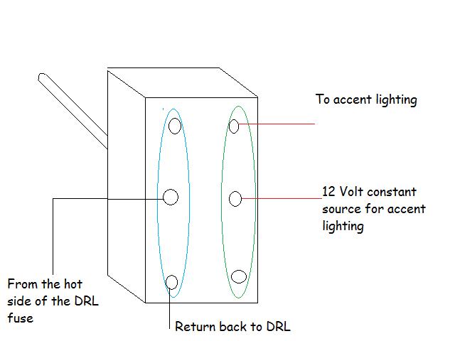
using a dpdt on off on switch -- posted image.

Since you are using this switch to essentially eliminate the fuse on the DRL circuit, you will need to put an in-line fuse holder with a 7.5 amp  fuse on the line leading to the switch.  You will need to use a volt meter to determine which of the 2 contacts for the fuse is the hot one.  You must attach the fuse holder to the wire that is inserted into the hot connection. 

You also need to fuse the constant connection for the accent lighting.  

The green and blue loops are just there to show you the 2 seperate poles of the switch


Sorry, you can NOT post a reply.
This topic is closed.

  Printable version Printable version Post ReplyPost New Topic
You cannot post new topics in this forum
You cannot reply to topics in this forum
You cannot delete your posts in this forum
You cannot edit your posts in this forum
You cannot create polls in this forum
You cannot vote in polls in this forum

  •  
Search the12volt.com
Follow the12volt.com Follow the12volt.com on Facebook
Tuesday, May 14, 2024 • Copyright © 1999-2024 the12volt.com, All Rights Reserved Privacy Policy & Use of Cookies
Disclaimer: *All information on this site ( the12volt.com ) is provided "as is" without any warranty of any kind, either expressed or implied, including but not limited to fitness for a particular use. Any user assumes the entire risk as to the accuracy and use of this information. Please verify all wire colors and diagrams before applying any information.

Secured by Sectigo
the12volt.com spacer
Support the12volt.com
Top
the12volt.com spacer