the12volt.com spacer
icon

08 crown vic issues


Post ReplyPost New Topic
< Prev Topic Next Topic >
rls13 
Member - Posts: 8
Member spacespace
Joined: February 08, 2014
Location: Montana, United States
Posted: October 10, 2014 at 4:01 PM / IP Logged Link to Post Post Reply Quote rls13
I just finished installing a Viper 5704v into a 08 Ford Crown Vic.
I hooked the blue (trunk instant trigger -) wire to the brown / white wire at the LCM. Opening the trunk with a key will properly set off the alarm just as it should, however after arming the system, the alarm will go off within 30 minutes or so and say the it was the trunk "zone" that was triggered even though it wasn't. The car is a CVPI so it didn't have the key less entry option, if it makes any difference. I suspect that there is a pulse or something being put out by the car that is triggering the alarm falsely.
I clipped the blue wire and tested to see if the alarm would still get triggered after 15-30 minutes and it doesn't. It has sat for hours with no false alarm. I would like to be able to reattach the wire, but need to know what is causing the false alarm.
Can I diode isolate this trigger to allow the negative pin switch signal to trip the alarm, but not allow whatever else is coming down the line? Or is there just some CVPI trick that is well known and I'm just not finding? There is no other pin switches or sensors connected to the blue wire, only the trunk pin.
Thanks.
kreg357 
Platinum - Posts: 7,783
Platinum spaceThis member has made a donation to the12volt.com. Click here for more info.spaceThis member has been recognized as an authority in Electrical Theory. Click here for more info.spaceThis member has been recognized as an authority in Mobile Security and Convenience. Click here for more info.spacespace
Joined: January 30, 2009
Location: Pennsylvania, United States
Posted: October 11, 2014 at 9:33 AM / IP Logged Link to Post Post Reply Quote kreg357

Think you are on the right track with diode isolation.  Check out DEI Tech Tip 1076 :  https://www.the12volt.com/installbay/file.asp?ID=514

Soldering is fun!
rls13 
Member - Posts: 8
Member spacespace
Joined: February 08, 2014
Location: Montana, United States
Posted: October 11, 2014 at 10:10 AM / IP Logged Link to Post Post Reply Quote rls13
Yeah I finally found another post about a 99 Grand Prix on this forum this morning, where the poster had the same issue and was recommended to use the same fix. It sounded like he ended up diode isolating a different wire that had to do with the trunk courtesy light, but with the same results.
I diode isolated the trunk trigger input to the alarm with the cathode away from the alarm box, but again got false triggers.
I don't know if it is the LCM sending the ground pulse or the BCM, and I don't have a good wiring diagram for the car (the Chilton's manual is extremely vague...), so without knowing which module or where the BCM makes its connection in the circuit, the only sure fire way to do what is in that DEI 1076 document, is to run a wire all the way back to the trunk?
Here is an idea I was toying with also. If I could attach images it would be a little easier to explain. I HAVE NOT actually wired this stuff up. It is just a theory.
-Cut Brown / White trunk trigger wire
-Run trigger side to Relay #1 Pin 30 and and Pin 85, plus Relay #2 Pins 30 and 85.
-Run LCM side to Relay #1 Pin 87a(N.C) and Relay #2 Pin 87(N.O)
-Connect fused constant 12VDC (+) to both Relay Pins 86.
-Connect alarm trunk trigger input (-) to Relay #1 Pin 87(N.O)
This seems to allow the BCM and LCM to have a closed connection at all times to the physical trunk trigger, allows the courtesy light to function as normal and isolates the alarm trunk trigger input from the BCM and LCM so that the negative pulse that occurs roughly 30 minutes from arming the alarm, has no effect on it.
Please feel free to check my "math" as I don't claim to be an alarm wiz...
rls13 
Member - Posts: 8
Member spacespace
Joined: February 08, 2014
Location: Montana, United States
Posted: October 11, 2014 at 10:24 AM / IP Logged Link to Post Post Reply Quote rls13
Actually it appears that I can upload pics. I will try anyway.
I also had the thought that could just do away with relay 2 completely and just put a diode between pin 87 and 87a, with the cathode on 87?
kreg357 
Platinum - Posts: 7,783
Platinum spaceThis member has made a donation to the12volt.com. Click here for more info.spaceThis member has been recognized as an authority in Electrical Theory. Click here for more info.spaceThis member has been recognized as an authority in Mobile Security and Convenience. Click here for more info.spacespace
Joined: January 30, 2009
Location: Pennsylvania, United States
Posted: October 11, 2014 at 10:59 AM / IP Logged Link to Post Post Reply Quote kreg357

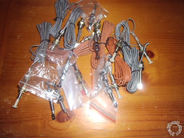
Perhaps the more direct way is easiest.  Install a separate pin switch in the trunk for the Viper alarm and leave the vehicle wiring alone.  The rust issues should be less in the trunk environment. I have a pot full of the hood pin switches that are included in most R/S kits ( I use mercury switches if the vehicle doesn't have a viable hood pin switch ).  I can send you a couple.  08 crown vic issues -- posted image.   Leftovers from recent installs...

08 crown vic issues -- posted image.

Soldering is fun!
rls13 
Member - Posts: 8
Member spacespace
Joined: February 08, 2014
Location: Montana, United States
Posted: October 11, 2014 at 5:29 PM / IP Logged Link to Post Post Reply Quote rls13
I appreciate the offer but I think I am just going to go the diode route that is in the DEI 1076 document. While I was out and about today, it dawned on me that my relay idea will probably not work. Because the negative pulse send from the (I am guessing LCM, since I can't find anything about a BCM on Crown Vic's) will simply find its way back to the alarm by triggering the relay coil since it is tied to it in reverse. Once the coil is energized then it will most likely latch Pin 30 to Pin 87 and then set off the alarm. The only way is to install a diode as Doc. 1076 shows...
So I just went and picked up more.
Thanks for the help.
ensjesse 
Member - Posts: 1
Member spacespace
Joined: September 07, 2015
Posted: September 08, 2015 at 11:05 AM / IP Logged Link to Post Post Reply Quote ensjesse
kreg357 wrote:

Think you are on the right track with diode isolation.  Check out DEI Tech Tip 1076 :  https://www.the12volt.com/installbay/file.asp?ID=514

Thank you for the info! I have a 2010 CVPI and not only does the LCM ground the trunk trigger but also the headlight switch as well. I have them connected to my CS7000 and am getting false inputs on the headlight and trunk warnings after 30 minutes when the battery saver mode kicks in. Only thing that will be a bummer here is I am not really wanting to sever the stock wiring. An alternate trunk trigger may be good as you suggested but what about my headlamp switch? Is there any clean way to insert the diode in path and keep a good connection? I don't have much room to solder around the LCM.
Thanks for the information.
Jesse
howie ll 
Pot Metal - Posts: 16,466
Pot Metal spacespace
Joined: January 09, 2007
Location: United Kingdom
Posted: September 08, 2015 at 1:26 PM / IP Logged Link to Post Post Reply Quote howie ll
Tried relays, 10k pullup resistors and diodes, the last is the only effective method.

If you wish to post a reply to this topic, you must first login.
If you are not already registered, you must first register.

  Printable version Printable version Post ReplyPost New Topic
You cannot post new topics in this forum
You cannot reply to topics in this forum
You cannot delete your posts in this forum
You cannot edit your posts in this forum
You cannot create polls in this forum
You cannot vote in polls in this forum

  •  
Search the12volt.com
Follow the12volt.com Follow the12volt.com on Facebook
Thursday, May 2, 2024 • Copyright © 1999-2024 the12volt.com, All Rights Reserved Privacy Policy & Use of Cookies
Disclaimer: *All information on this site ( the12volt.com ) is provided "as is" without any warranty of any kind, either expressed or implied, including but not limited to fitness for a particular use. Any user assumes the entire risk as to the accuracy and use of this information. Please verify all wire colors and diagrams before applying any information.

Secured by Sectigo
the12volt.com spacer
Support the12volt.com
Top
the12volt.com spacer