the12volt.com spacer
icon

94 Altima, Boa remote start


Post ReplyPost New Topic
< Prev Topic Next Topic >
amargari 
Member - Posts: 4
Member spacespace
Joined: December 26, 2005
Location: United States
Posted: December 26, 2005 at 3:47 PM / IP Logged  

I was given a BOA Remote Start System with Keyless Entry kit for Christmas.  I read the installation manual and did some research about installing this system. 

I am a little confused about what to do about the Second Starter input.  I went to the 1994 Nissan Wiring Information on this site, but found conflicting information.  The one link on this site and the DEI site displays the Second Starter as blk/grn.  The other link on this site displays the Second Ignition as BLACK/ Green.  Which one is correct? 

My kit comes with connections for Ignition 1 and Ignition 2.  Do I hook my unit's 2nd ignition connection to the BLACK/ Green wire?

I read about the Accessory relay and understand how to wire this.  I only need to know what amperage relay is required for this?  Should I use a DEI 8616 or a DEI 8617.

Thanks In Advance

Mike M2 
Platinum - Posts: 2,652
Platinum spacespace
Joined: June 29, 2005
Location: United States
Posted: December 26, 2005 at 4:03 PM / IP Logged  
BLACK/ green is the second starter. Also notice that the wires change colors at the plug fastened under the steering column and most sites will list both. I don't believe there was a second ignition wire on that body style at all, only the funky accessory wire that needs keyswitch isolation.  You could utilize the second ignition relay for the second starter by changing the input wire on the ribbon cable. Just remove the wire that's on it now and tap off the purple wire to feed this relay too.
Mike M2
Tech Manager
CS Dealer Services
amargari 
Member - Posts: 4
Member spacespace
Joined: December 26, 2005
Location: United States
Posted: January 01, 2006 at 3:16 PM / IP Logged  

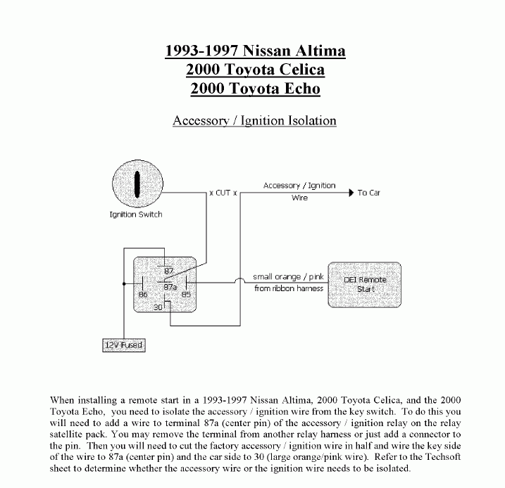
Ok,  The car starts but I am having accessory wire issues.  I wired the accessory wires like this:

94 Altima, Boa remote start -- posted image.

When I remote start the car, my accessories don't work.  I used my test light to test the relay and noticed that terminals 85, 86, and 87 have voltage.  87a and 30 are dead.  Is the above diagram right?  If I bypass the relay and connect 30 and 85, I get power to the accessories.

Also, my parking lights flash when the car is in remote start mode.  Is this normal for this unit?

-Thanks

amargari 
Member - Posts: 4
Member spacespace
Joined: December 26, 2005
Location: United States
Posted: January 01, 2006 at 4:58 PM / IP Logged  

OK,

I went and researched relays and the need for keyswitch isolation and think I know what is wrong.  Apparently,  something bad happens when the remote start energizes the keyswitch on the accessory line.  That means that either the switch or the remote start needs to have current to the accessory line but not both. 

So I think that there has to be a switch put in line to guarantee that they are not both energizing the accessory line at the same time.  So I think the following wiring diagram will work:

85 has to go to ground

30 Goes to the accessory line after the cut
87a Goes to the accessory line that terminates at the ignition switch
87 and 86 go to the accessory output of the remote starter unit.

The system should have continuity across the 30 and 87a terminals when the remote start is off.  This should allow the ignition switch to control the accessory line.

The system should have continuity across the 30 and 87 terminals when the remote start system is energized.  The switch should then be isolated. 

Does this sound correct?

mo12v 
Platinum - Nominee - Posts: 2,748
Platinum - Nominee spaceThis member consistently provides reliable informationspace
Joined: September 30, 2003
Location: Afghanistan
Posted: January 01, 2006 at 8:31 PM / IP Logged  

Are you SURE you are using a SPDT ( Single Pole Double Throw ) Relay??

Doesn't sound like it........
Where did you get Relay?

PIN 30 should have Power with Ignition & R / S

MO
Don't Learn from Others Mistakes
You Might Be the One That Knows.
amargari 
Member - Posts: 4
Member spacespace
Joined: December 26, 2005
Location: United States
Posted: January 01, 2006 at 10:23 PM / IP Logged  

I got the relay from Parts Express.  The part number was 330-073, 12VDC AUTOMOTIVE RELAY SPDT 30A.  Here is the link www.partsexpress.com/pe/pshowdetl.cfm?&DID=7&Partnumber=330-073

I'm new to relays, but how can the DEI example work when there isn't a ground wired to any of the terminals on the relay and all the triggers are positive triggers from the switch and the remote start?

-Thanks

KarTuneMan 
Platinum - Posts: 7,056
Platinum spaceThis member has made a donation to the12volt.com. Click here for more info.spaceThis member consistently provides reliable informationspace
Joined: December 14, 2004
Location: Isle Of Man
Posted: January 02, 2006 at 12:25 AM / IP Logged  
mo12v wrote:

Are you SURE you are using a SPDT ( Single Pole Double Throw ) Relay??

Doesn't sound like it........
Where did you get Relay?

PIN 30 should have Power with Ignition & R / S

Mo has the answer.....................or at least a good question


Sorry, you can NOT post a reply.
This topic is closed.

  Printable version Printable version Post ReplyPost New Topic
You cannot post new topics in this forum
You cannot reply to topics in this forum
You cannot delete your posts in this forum
You cannot edit your posts in this forum
You cannot create polls in this forum
You cannot vote in polls in this forum

  •  
Search the12volt.com
Follow the12volt.com Follow the12volt.com on Facebook
Tuesday, May 14, 2024 • Copyright © 1999-2024 the12volt.com, All Rights Reserved Privacy Policy & Use of Cookies
Disclaimer: *All information on this site ( the12volt.com ) is provided "as is" without any warranty of any kind, either expressed or implied, including but not limited to fitness for a particular use. Any user assumes the entire risk as to the accuracy and use of this information. Please verify all wire colors and diagrams before applying any information.

Secured by Sectigo
the12volt.com spacer
Support the12volt.com
Top
the12volt.com spacer