the12volt.com spacer
icon

diodes


Post ReplyPost New Topic
< Prev Topic Next Topic >
ihkili18 
Copper - Posts: 108
Copper spacespace
Joined: November 07, 2006
Posted: December 17, 2006 at 6:54 AM / IP Logged  
Hi everyone I am trying to figure out exactly what diodes are and when and how they are used. Any explanation especially a detailed one would be appreciated.thanx
rudydapimp 
Copper - Posts: 390
Copper spacespace
Joined: February 27, 2006
Location: United States
Posted: December 17, 2006 at 7:21 AM / IP Logged  
https://www.the12volt.com/diodes/diodes.asp
ihkili18 
Copper - Posts: 108
Copper spacespace
Joined: November 07, 2006
Posted: December 17, 2006 at 7:25 AM / IP Logged  
thanx for the reply. i read it but it still doesnt explain to me how i would wire a grand am that only has a single lock/unlock wire. how do i get the doors to unlock when i press the unlock button on the remote and so on. i see people talking about resistors and diodes and the door lock diagrams are confusing to someone who has never installed an alarm/remote start before.thanx
Mike M2 
Platinum - Posts: 2,652
Platinum spacespace
Joined: June 29, 2005
Location: United States
Posted: December 17, 2006 at 9:30 AM / IP Logged  
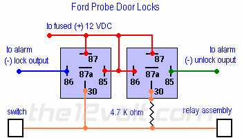
 I can't find a diagram on the Grand Am, but it wires like the Ford Probe with two differences. First, instead of 87 going to 12volts they will go to ground. Second, the 4.7k resistor needs to be 1500ohm. Everything else stays the same, no diodes are needed.
diodes -- posted image.
 
Mike M2
Tech Manager
CS Dealer Services
rudydapimp 
Copper - Posts: 390
Copper spacespace
Joined: February 27, 2006
Location: United States
Posted: December 17, 2006 at 9:56 AM / IP Logged  
http://www.directechs.com/techtips/pdfs/resources/security/directed_techtips/1041.pdf
ainami 
Member - Posts: 28
Member spacespace
Joined: November 17, 2006
Location: United States
Posted: December 17, 2006 at 10:54 AM / IP Logged  
I know what resistors are. But what does it do in that schematic.
Also sometimes I see resitors between 85 and 86. What is the purpose.
alexlloyd 
Member - Posts: 24
Member spacespace
Joined: April 06, 2006
Location: Canada
Posted: December 18, 2006 at 10:28 AM / IP Logged  

The item between 85 and 86 won't be a resistor it will be a diode. In order to explain it I will need to go a little more in depth.

To generate electricity, a conductor is passed through a magnetic field and depending on the size of the conductor, the strength of the magnetic field and the direction of each in relation to each other, a voltage is produced. This is power generation 101 (circuit operation will force us back here in a minute).

The second phenomenon about eletricity is that when you activate a relay (or any coil) with electricity, it builds a magnetic field around that coil (seeing the connection??); (power consumption 101).

When the power is removed from the coil (circuit), the magnetic field rapidly collapses (which immitates motion) and generates a reverse voltage within the circuit (power generation 101 in reverse). With old technology this reverse voltage could be ignored as we were dealing with large and very UN-sensitive (stable) components. With the new technology, these circuits are very sensitive and susceptible to operation by erroneous inputs due to their engineering. Diodes employed across a coil prevent this reverse voltage pulse from generating erroneous inputs by electronically shorting out the coil.

Diode theory... a diode, through it's construction, will only allow current to flow in one direction. This results in the diode appearing in the circuit one way as a broken wire and the other direction as a dead short. By installing the diode accross the coil, when energized the coil cannot see the diode but when the circuit is de-activated, the diode shorts out the reverse polarity generation and securley shuts down the relay.

More info and applications are on the links to the left under "Forums""Relays" which will lead you here https://www.the12volt.com/relays/page5.asp


Sorry, you can NOT post a reply.
This topic is closed.

  Printable version Printable version Post ReplyPost New Topic
You cannot post new topics in this forum
You cannot reply to topics in this forum
You cannot delete your posts in this forum
You cannot edit your posts in this forum
You cannot create polls in this forum
You cannot vote in polls in this forum

  •  
Search the12volt.com
Follow the12volt.com Follow the12volt.com on Facebook
Tuesday, May 14, 2024 • Copyright © 1999-2024 the12volt.com, All Rights Reserved Privacy Policy & Use of Cookies
Disclaimer: *All information on this site ( the12volt.com ) is provided "as is" without any warranty of any kind, either expressed or implied, including but not limited to fitness for a particular use. Any user assumes the entire risk as to the accuracy and use of this information. Please verify all wire colors and diagrams before applying any information.

Secured by Sectigo
the12volt.com spacer
Support the12volt.com
Top
the12volt.com spacer