the12volt.com spacer
icon

clutch safety switch


Post ReplyPost New Topic
< Prev Topic Next Topic >
y2j514 
Copper - Posts: 94
Copper spacespace
Joined: April 26, 2007
Location: Quebec, Canada
Posted: November 01, 2007 at 8:17 PM / IP Logged  

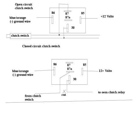
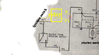
Ok so I hope to install an alarm system/car starter (scytek visionguard 8000-m) on my car (1997 Pontiac Sunfire, manual) tomorrow.  I was just wondering exactly to how I would do the clutch safety switch.  The instructions give two different options and I dont know which is better suited for my car: open circuit, or closed circuit.  Personally, I have a hunch its closed circuit.  So before I go chopping up my starting system I just want to verify with someone. My first picture is the diagram for open and closed circuit the manual has, and the second picture is what I believe I need to do.  If I am wrong could someone please correct me.  Thank you!

clutch safety switch -- posted image.

clutch safety switch -- posted image.

sorry for picture quality...good ol 30kb limit.  anyways so ya. does that last picture look right?

Thank you so much for your help in advance!

KarTuneMan 
Platinum - Posts: 7,056
Platinum spaceThis member has made a donation to the12volt.com. Click here for more info.spaceThis member consistently provides reliable informationspace
Joined: December 14, 2004
Location: Isle Of Man
Posted: November 01, 2007 at 8:47 PM / IP Logged  

Connect your remote starter "starter output" directly to the purple wire on the clutch switch.

Your clutch is now bypassed. Remote start's EVERY TIME. If your remote start isn't manual safe, it will start in gear.

I don't know the skyteck line, and usually look before I post.... but I trust you, and hope your smart.clutch safety switch -- posted image.

y2j514 
Copper - Posts: 94
Copper spacespace
Joined: April 26, 2007
Location: Quebec, Canada
Posted: November 03, 2007 at 7:00 PM / IP Logged  

Ok well I havent gotten to the clutch part yet.  But I have a few questions.  I can not for the life of me find my tach wire.  I've read in many places saying that its the white wire in the engine harness next to the battery, beneath the radiator hose ontop of the transaxle.  In that general area all I see is one thick wire loom, and there is no white wire there.  If anyone has a picture that would be...AWEEESOME! ;) Secondly, I can't find anywhere what color the parking brake input wire is.  Does anyone know/where can I find?  Another one I need to find is the "+12V ignition input"  the description is shows 12V when ignition is in the "on" position, and while cranking the starter.  The Voltage must not drop when the car is starting.  For the sunfire the 3 ignition wires are Pink, White and Brown.  2 of the wires drop to about 10V and the pink one drops to like nearly nothing, I forget the exact value.  One more tiny tidbit, the horn wire is indicated as the black wire in the ignition harness. There are 2 black wires in the ignition harness, and when they are unplugged the horn still honks, so I dont think it is thoses.  I could easily splice the horn wire underneath the hood, because I can find that one easily, but I'd rather do it under the dash.

so

1)Tach wire

2)Hand brake wire
3) 12V ignition input (voltage does not drop when starting)
4) Horn wire under dash

Thank you very much for all of your help guys, appreciate it!

tedmond 
Gold - Posts: 4,610
Gold spaceThis member has been recognized as an authority in Mobile Security and Convenience. Click here for more info.spacespace
Joined: January 06, 2007
Location: Ontario, Canada
Posted: November 03, 2007 at 8:52 PM / IP Logged  

)Tach wire

2)Hand brake wire
3) 12V ignition input (voltage does not drop when starting)
4) Horn wire under dash

1) White @ engine harness on front of engine comming over transmission

2) open centre consol and reach down to handbrake wire, cut and tap into wire.
3) not sure why you concerned about the voltage is dropping. voltage always drops during start then goes back to 12 - 14.4 volts.

y2j514 
Copper - Posts: 94
Copper spacespace
Joined: April 26, 2007
Location: Quebec, Canada
Posted: November 03, 2007 at 9:00 PM / IP Logged  

1) Tach wire...like i said, thats what I read, but I cant seem to find.  I might be retarted or something because it sounds so easy, but I just don't see it.

2)Hand brake wire...thank you
3)Thats what I thought too but the installation manual specifically says:
"Pin 5 YELLOW WIRE: +12 V Ignition input.  The yellow wire must connect to a main ignition wire at the ignition harness.  This wire must show +12V when the ignition is on and while cranking the starter.  The Voltage must not drop when the car is starting"

So I was just simply trying to follow the instructions, any suggestion?

4) Horn wire is under the dash but as I said, the 2 black wires I suspected were disconnected and the horn still worked, so obviously not thoses. Do you know if it connects to the main ignition harness or if it connect to same area as either the hazard or the signal stick or the whipers stick?

KarTuneMan 
Platinum - Posts: 7,056
Platinum spaceThis member has made a donation to the12volt.com. Click here for more info.spaceThis member consistently provides reliable informationspace
Joined: December 14, 2004
Location: Isle Of Man
Posted: November 04, 2007 at 12:04 AM / IP Logged  

Your hand brake wire is lt.blue. It can be found in 2 different places. The easiest to get to is the switch at the brake handle itself. It's negative. It can also be found behind the guage cluster at the idiot light. The horn is in a grey plug above the column. balck wire. Ign 1 is pink, ign.2 is white.

Don't unplug things to test. Use a multi-meter.

tedmond 
Gold - Posts: 4,610
Gold spaceThis member has been recognized as an authority in Mobile Security and Convenience. Click here for more info.spacespace
Joined: January 06, 2007
Location: Ontario, Canada
Posted: November 04, 2007 at 8:57 AM / IP Logged  

"Pin 5 YELLOW WIRE: +12 V Ignition input.  The yellow wire must connect to a main ignition wire at the ignition harness.  This wire must show +12V when the ignition is on and while cranking the starter.  The Voltage must not drop when the car is starting"

all alarms have a 12v ignition input, it is only used to trigger the alarm if the car was armed; and for some reason the ignition was powered by key or hotwire. 

y2j514 
Copper - Posts: 94
Copper spacespace
Joined: April 26, 2007
Location: Quebec, Canada
Posted: November 12, 2007 at 11:10 PM / IP Logged  

Thank you everyone for all of your help.  I am 99% complete.  I have everything wired,  I verified all of my wiring, I installed my electric door actuators, and its ALMOST ready to go.  The one thing I have left is the stupid tachometer wire.  It is elluding me.  I have a 1997 pontiac sunfire with a manual transmission.  I have read time and time again that it is the white wire in the engine harness next to the battery, under the radiator hose, above the transaxle.  Thats all fine and dandy, but the wire colors are faded and dirty.  I tested every wire that appears that it could have been white.  Is there another spot I can find the same wire?  Like going through the firewall, or going into the block like connection just to the left of the drivers shock? 

Just to verify I am looking for a negative AC current that varries with the throttle from about 3-7 volts, right?  Man I feel handicaped...


Sorry, you can NOT post a reply.
This topic is closed.

  Printable version Printable version Post ReplyPost New Topic
You cannot post new topics in this forum
You cannot reply to topics in this forum
You cannot delete your posts in this forum
You cannot edit your posts in this forum
You cannot create polls in this forum
You cannot vote in polls in this forum

  •  
Search the12volt.com
Follow the12volt.com Follow the12volt.com on Facebook
Monday, April 29, 2024 • Copyright © 1999-2024 the12volt.com, All Rights Reserved Privacy Policy & Use of Cookies
Disclaimer: *All information on this site ( the12volt.com ) is provided "as is" without any warranty of any kind, either expressed or implied, including but not limited to fitness for a particular use. Any user assumes the entire risk as to the accuracy and use of this information. Please verify all wire colors and diagrams before applying any information.

Secured by Sectigo
the12volt.com spacer
Support the12volt.com
Top
the12volt.com spacer