the12volt.com spacer
icon

remote windows, doors


Post ReplyPost New Topic
< Prev Topic Next Topic >
dan epps 
Member - Posts: 5
Member spacespace
Joined: May 03, 2009
Location: Georgia, United States
Posted: May 03, 2009 at 1:28 PM / IP Logged  

I am buiklding a 1934 Ford pickup streetrod with (of course) all the modern amenities.  It has shaved doors (no handles) and will use a remote transciever for opening the doors.

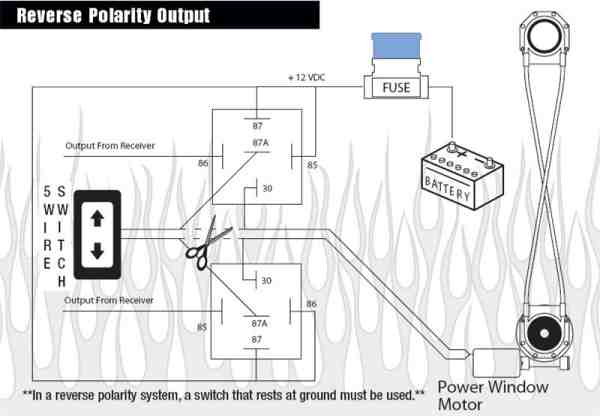
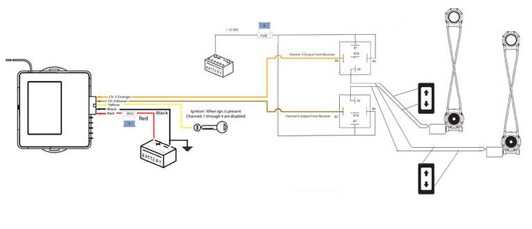
In addition to the doors, I would like to be able to open/close both windows with the remote.  I have install instructions for doing this in conjunction with the manual switch for each window.  It has two relays for each window--one for opening and one for closing.

This is all straightforward enough but, I want to modify the design a bit and don't know how to achieve what I want to do.

I want to be able to control each window independently using the manual five-wire switches (no problem, witing harness included with window kit).  I want to control both windows at the same time (not independently) using the remote.

I know I can easily connect both windows to pin 30 of the relays so that both work together with the remote (as long as I use a large enough fuse).  Where I am lost, however, is how to include the five-wire switches in the mix so they can control the windows independently.  If I just wire the switches as if the remote (thus the relays) doesn't exist, will that produce feedback to the relays and cause damage/unpredictable results?

Summary...I want to have only two relays, one to open and one to close both windows at the same time with the remote.  I also want to be able to use the manual five-wire switches to open/close each window.  Can this be done and how?

remote windows, doors -- posted image.

Thanks,
Dan
dan epps 
Member - Posts: 5
Member spacespace
Joined: May 03, 2009
Location: Georgia, United States
Posted: May 03, 2009 at 1:30 PM / IP Logged  

Wow, that image sure distorted! remote windows, doors -- posted image.

It is a standard five-wire, reversing diagram.

Thanks,
Dan
the12volt 
Administrator - Posts: 3,955
Administrator spaceThis member has made a donation to the12volt.com. Click here for more info.spaceThis member has been recognized as an authority in Electrical Theory. Click here for more info.spaceThis member has been recognized as an authority in Mobile Audio and Video. Click here for more info.spaceThis member has been recognized as an authority in Mobile Security and Convenience. Click here for more info.spacespace
Joined: March 07, 2002
Location: Louisiana, United States
Posted: May 03, 2009 at 3:12 PM / IP Logged  
Image fixed ;)
remote windows, doors -- posted image. the12volt • Support the12volt.com
howie ll 
Pot Metal - Posts: 16,466
Pot Metal spacespace
Joined: January 09, 2007
Location: United Kingdom
Posted: May 03, 2009 at 5:17 PM / IP Logged  
Top of my head, get rid of the relays, run the 5 wire switches directly to the motors then use a 530t from DEI via the two leads that went to 86 on your relays (actually they should have gone to 85 with the power to 86 but not relevant) . That will give you normal or one touch up and down from the switches + remote conttrol up and down.
dan epps 
Member - Posts: 5
Member spacespace
Joined: May 03, 2009
Location: Georgia, United States
Posted: May 03, 2009 at 5:33 PM / IP Logged  

howie ll wrote:
Top of my head, get rid of the relays, run the 5 wire switches directly to the motors then use a 530t from DEI via the two leads that went to 86 on your relays (actually they should have gone to 85 with the power to 86 but not relevant) . That will give you normal or one touch up and down from the switches + remote conttrol up and down.

Well, for starters, I already have a SPAL control unit for the door openers that I can't (don't want to) replace, so how would the 530t work into the equation?

The diagram is a bit fuzzy...power goes to 85 on the first relay (up) and 86 on the second (down).  The remote trigger goes to 86 on the first relay (up) and 85 on the second (down).  In a "normal" installation this would be repeated on two additional channels for the other window.

What I'm trying to do is use one channel to open both windows and another to close both while keeping the manual switch for each window.

Thanks,
Dan
dan epps 
Member - Posts: 5
Member spacespace
Joined: May 03, 2009
Location: Georgia, United States
Posted: May 04, 2009 at 7:12 AM / IP Logged  

Maybe this diagram will help illustrate what I'm trying to do...

remote windows, doors -- posted image.

Thanks,
Dan
howie ll 
Pot Metal - Posts: 16,466
Pot Metal spacespace
Joined: January 09, 2007
Location: United Kingdom
Posted: May 04, 2009 at 12:58 PM / IP Logged  
You branch out from the lock  trigger wire (brown or violet at the Spal relay) add a DEI timer, set to 8 secs and feed this to the orange on the 530t. To vent the windows, you've got to hope the keylesss entry has an aux output. You wiil be using 2 5wire Spal swiches, or 2 drive side, one passenger side and once AGAIN the 530t goes to the motor wires and the relays are put aside for something else.
dan epps 
Member - Posts: 5
Member spacespace
Joined: May 03, 2009
Location: Georgia, United States
Posted: May 04, 2009 at 3:05 PM / IP Logged  

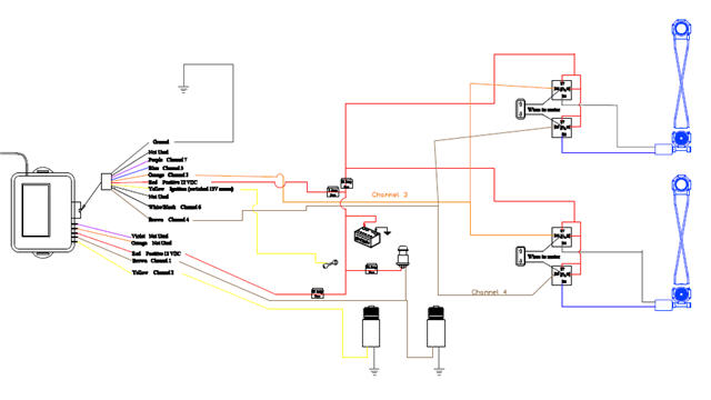
Okay, here is the diagram SPAL tech support sent that does what I want without the need for any additional modules of any kind.  Thanks for the suggestions.

remote windows, doors -- posted image.

Thanks,
Dan

Sorry, you can NOT post a reply.
This topic is closed.

  Printable version Printable version Post ReplyPost New Topic
You cannot post new topics in this forum
You cannot reply to topics in this forum
You cannot delete your posts in this forum
You cannot edit your posts in this forum
You cannot create polls in this forum
You cannot vote in polls in this forum

  •  
Search the12volt.com
Follow the12volt.com Follow the12volt.com on Facebook
Monday, May 27, 2024 • Copyright © 1999-2024 the12volt.com, All Rights Reserved Privacy Policy & Use of Cookies
Disclaimer: *All information on this site ( the12volt.com ) is provided "as is" without any warranty of any kind, either expressed or implied, including but not limited to fitness for a particular use. Any user assumes the entire risk as to the accuracy and use of this information. Please verify all wire colors and diagrams before applying any information.

Secured by Sectigo
the12volt.com spacer
Support the12volt.com
Top
the12volt.com spacer