Relays / Special Applications
Below are just a dozen of the many special relay applications I've created for this site. Most,
if not all, may be found in the
Relay Diagrams - Quick Reference section.
Constant to Momentary Output
 Constant to Momentary Output
 |
The capacitor allows the
coil of the relay to be energized until the capacitor stores a charge,
thus de-energizing the coil. The resistor bleeds off the charge of the
capacitor when positive voltage is removed from the other side of the coil. You
can increase the output time by simply changing the value of the capacitor.
This one will give you about a 1/2 second output.
 |
|
|
Momentary to Constant Output
|
Momentary to Constant Output |
Once activated by the relay on the left, the relay's coil on
the right will stay energized until either ground or 12v(+) is removed.
You can do this with another relay. Or try connecting to a 12v(+) switched
source instead of a constant one. Or you can have a door trigger activate
a relay to break continuity. The variations are practically endless.
 |
|
|
Pulsed to Steady Output
|
Pulsed to Steady Output |
If you have cornering lights and want them to come on only when your turn signal
is on and you do not have a steady output, use the following for each side. This will give you a steady output
while the turn signal is on. Increasing the size of the capacitor will give you a longer output if needed.
 |
|
|
Connecting Additional Devices to the Remote Turn On Wire
|
Connecting Additional Devices to the Remote Turn On Wire |
Using a 30 amp SPDT relay, connect terminal #87 to constant 12 volts positive with a fuse
rated to the sum of the additional accessories you've added and the components you need to turn on.
(If you have two fans rated at 5 amps each and a neon light rated at 10 amps, you would use a 20 amp
fuse plus 200 ma for each amplifier and processor.) Connect terminal #85 to ground, terminal #86 to
the remote turn on wire from the head unit, and terminal #30 to each accessory with an appropriate fuse.
A fuse (not shown) could also be used between the output of the relay (#30) and the remote turn
on wire of the amplifiers and/or processors for extra precaution.
 |
|
|
Stereo to Bridged Mono Switched Outputs
|
Stereo to Bridged Mono Switched Outputs |
If your amplifier is capable of running in dual mode or mono,
and is configured to run mono by using the left channel positive and the
right channel negative outputs, then the diagram to switch between stereo
and mono to the same pair of speakers (mostly woofers) is as shown below.
Remember this will decrease the impedance by 1/2 and in
theory double
the power output of the amplifier.
Be sure to check the specifications of your amplifier first.
 |
|
|
Switching from Series to Parallel and Back
|
Switching from Series to Parallel and Back |
When the relays are at rest (normally closed position) the woofer coils are wired in series.
When ground is applied to each coil (energizing the relay coils), the voice coils are wired in parallel.
With 2 four ohm voice coils you'll have an 8 ohm load at rest and a 2 ohm load when the relay coils are energized.
For each dual voice coil woofer that you want to change from series to parallel, you'll need two relays for each.
They can all be controlled from the same switch.
 |
|
|
Single Pulse to Lock and Unlock
|
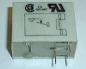
Single Pulse to Lock and Unlock |
Using a mechanical latching relay like the PCB latching relay pictured below on the left, you can
use a single negative output to alternately lock and unlock the doors. The mechanical latching relay only requires it's
coil to be momentarily energized to change and maintain the opening or closing of it's contacts. The SPDT relay
will provide a dedicated negative output for lock when the coil is energized and a dedicated output for unlock when it is not energized.
|
|
|
Switching from Stereo to Bridged Mono and Series to Parallel
|
Switching from Stereo to Bridged Mono and Series to Parallel |
Combining the two configurations above with 4 woofers or 2 DVC woofers, you can change from stereo to mono and from series to parallel.
Switch A (-) is to switch between series and parallel. Switch B (-) is to switch between stereo and
mono. With both switches off, the amp is wired in stereo and each pair of woofers, top and bottom, are wired in series.
*If your amplifier configuration for stereo and mono are different than shown, this obviously
will not work. Be sure to check the specifications of your amplifier first.
 |
|
|
One Channel to Multiple Outputs
|
One Channel to Multiple Outputs |
You can add multiple functions to an AUX output of an alarm or keyless entry
by adding a relay in series with the output wire as shown to any switch or accessory with an output.
Only one output can be active at anytime, the one first in the chain (bottom relay in diagram) will
have priority, so if you wanted to have the ignition from the key to have priority over the ignition from the remote start,
you would connect it to the first relay and the output of the remote start to the next and so on. Also pay attention to the top
relay shown. Terminal #87a (the default output) will be active only when none of the coils of the relays are energized. There are many other
accessories that can be used with this, including the remote turn on wire and/or power antenna wire of your head unit.
 |
|
|
Latched On/Off Output Using a Single Momentary Pulse
|
Latched On/Off Output Using a Single Momentary Pulse |
Similar to the momentary to constant configuration above, we can
engage and disengage the latched output with a single pulse from a switch or an output from an alarm or remote keyless entry.
The first pulse from the switch will engage the latch. The next pulse from the switch will disengage the latch.
 Here's the same configuration as the one above that you can use if you do not have any *diodes
available and/or only want to use SPDT relays. A negative output from an alarm,
remote keyless entry, or other device can be used in place of the switch shown in both of these diagrams.
Here's the same configuration as the one above that you can use if you do not have any *diodes
available and/or only want to use SPDT relays. A negative output from an alarm,
remote keyless entry, or other device can be used in place of the switch shown in both of these diagrams.
 |
|
|
Radio On Until Door Opened (Retained Accessory Power)
|
Radio On Until Door Opened (Retained Accessory Power) |
If you wish to keep the radio (or any other device that is powered by an accessory circuit) on until a door is opened, you can do so by creating a
latch when the accessory is turned on with the relay shown below on the left,
then breaking ground to the latch when a door is opened as shown with the relay below on the right.
While this will keep the radio on, the entire accessory circuit will see 12V+ until a door is opened with the key in the off position.
 If you want to prevent 12V+ from feeding back into the accessory circuit or have more than one device on this circuit and do not want all of them to stay powered, you can isolate the device you want to stay powered
by cutting the accessory wire going to it and adding two 1 amp diodes and an additional relay as shown below. The first diode near the top left of the diagram is to prevent 12V+ from going back into the accessory circuit.
The second diode between terminals 87 and 86 prevents the radio from pulling current through the first diode. If the second diode is not in place, the first diode will become toast. The additional relay is needed
to prevent the radio from turning off when the key is in the accessory position and a door is open.
If you want to prevent 12V+ from feeding back into the accessory circuit or have more than one device on this circuit and do not want all of them to stay powered, you can isolate the device you want to stay powered
by cutting the accessory wire going to it and adding two 1 amp diodes and an additional relay as shown below. The first diode near the top left of the diagram is to prevent 12V+ from going back into the accessory circuit.
The second diode between terminals 87 and 86 prevents the radio from pulling current through the first diode. If the second diode is not in place, the first diode will become toast. The additional relay is needed
to prevent the radio from turning off when the key is in the accessory position and a door is open.
 Below is the same set up as above for positive door triggers.
 |
|
|
Basic Remote Start Relay Diagram
|
Basic Remote Start Relay Diagram |
DO NOT INSTALL this or any other remote
start system not specifically designed for a manual transmission into a vehicle with a
STANDARD TRANSMISSION. The
consequences should be obvious, but in case you don't already know what they are,
property damage and serious injuries or even death could occur as a result.
Below is a basic relay remote start system.
It is not shown with any inhibits, nor a single trigger to activate
and deactivate it, and does not have "rev protection". You are
much better off with a system you can purchase from a local dealer or retailer.
They include many important safety features and come with a warranty, unlike
the one below. But if you must make one from relays, here are the basics
(shown below without the diodes across the coils). You will have
to customize this to work with the vehicle
you plan to install it into. Make note of each wire's function in the harness
connected to the back of the ignition switch. You will have to duplicate
these in order to have a successful installation.
Only advanced installers
should attempt this. I have installed several of these as a challenge and they are still
on the road today. I included timers and inhibits in them to perform the
same as a manufacturer's remote starter, but I still prefer to use theirs. Manufactured units take
far less time to install from start to finish and are a whole lot smaller.
 |
|
|

Follow the12volt.com
 Tuesday, April 28, 2026
• Copyright © 1999-2026 the12volt.com, All Rights Reserved
• Privacy Policy & Use of Cookies
Tuesday, April 28, 2026
• Copyright © 1999-2026 the12volt.com, All Rights Reserved
• Privacy Policy & Use of Cookies
Disclaimer:
*All information on this site ( the12volt.com ) is provided "as is" without any warranty of any kind, either expressed or implied, including but not limited to fitness for a particular use. Any user assumes the entire risk as to the accuracy and use of this information. Please
verify all wire colors and diagrams before applying any information.