


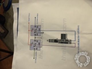
 The photos are relay circuit I used for my locks and the factory schematic for the power lock switches in my 2001 S10.
In my vehicle the lock signal wire at the switch is LT Blue and the unlock signal wire is White. I used a two relay circuit (actually got the circuit from The 12 Volt website). From the switch the lock circuit has 4 wires, orange for 12 volt positive, black for ground, Lt Blue got the lock command and White for the unlock command. The lock actuators are controlled by the relays. The signal wires go to the relay lock and unlock command terminal. Just be sure that you connect lock signal wire from driver and passenger switches to each other and to the relay lock trigger. Do the same with the unlock signal wires to the relay unlock trigger. The wires from the switches is 22 gauge. Use 14 gauge TXL to wire the relays. Fuse the orange wire from the switch at no more than 5 amps ( factory is 3 amp. I used a 5 amp in line fuse).
When I create my harness I use factory wire colors in TXL or GXL wire in factory gauge or one gauge heavier. I prefer to error on the side of safety. I lay my window regulators and lock actuators out on my work bench and use a 12 volt battery for power. If I make it work on the bench, it will work in the vehicle. I have wired many vehicle options using this procedure.
I must say that from about 99 up it is getting much harder to add options due to all of the computers in these vehicles and the tightness of the engine compartment. Good luck on your project. Hope the photos show up.
The photos are relay circuit I used for my locks and the factory schematic for the power lock switches in my 2001 S10.
In my vehicle the lock signal wire at the switch is LT Blue and the unlock signal wire is White. I used a two relay circuit (actually got the circuit from The 12 Volt website). From the switch the lock circuit has 4 wires, orange for 12 volt positive, black for ground, Lt Blue got the lock command and White for the unlock command. The lock actuators are controlled by the relays. The signal wires go to the relay lock and unlock command terminal. Just be sure that you connect lock signal wire from driver and passenger switches to each other and to the relay lock trigger. Do the same with the unlock signal wires to the relay unlock trigger. The wires from the switches is 22 gauge. Use 14 gauge TXL to wire the relays. Fuse the orange wire from the switch at no more than 5 amps ( factory is 3 amp. I used a 5 amp in line fuse).
When I create my harness I use factory wire colors in TXL or GXL wire in factory gauge or one gauge heavier. I prefer to error on the side of safety. I lay my window regulators and lock actuators out on my work bench and use a 12 volt battery for power. If I make it work on the bench, it will work in the vehicle. I have wired many vehicle options using this procedure.
I must say that from about 99 up it is getting much harder to add options due to all of the computers in these vehicles and the tightness of the engine compartment. Good luck on your project. Hope the photos show up.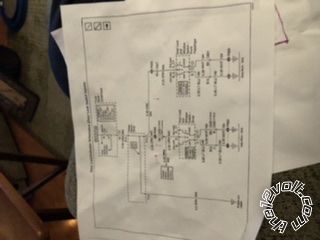
If you wish to post a reply to this topic, you must first login.
If you are not already registered, you must first register.
 Printable version


| You cannot post new topics in this forum You cannot reply to topics in this forum You cannot delete your posts in this forum You cannot edit your posts in this forum You cannot create polls in this forum You cannot vote in polls in this forum |

| Search the12volt.com |
Follow the12volt.com 
Friday, May 15, 2026 • Copyright © 1999-2026 the12volt.com, All Rights Reserved • Privacy Policy & Use of Cookies

Friday, May 15, 2026 • Copyright © 1999-2026 the12volt.com, All Rights Reserved • Privacy Policy & Use of Cookies
Disclaimer:
*All information on this site ( the12volt.com ) is provided "as is" without any warranty of any kind, either expressed or implied, including but not limited to fitness for a particular use. Any user assumes the entire risk as to the accuracy and use of this information. Please
verify all wire colors and diagrams before applying any information.
