Posted: March 14, 2005 at 7:31 PM / IP Logged
Posted: March 14, 2005 at 7:33 PM / IP Logged
Posted: March 14, 2005 at 11:15 PM / IP Logged
Sorry, you can NOT post a reply.
This topic is closed.
 Printable version


| You cannot post new topics in this forum You cannot reply to topics in this forum You cannot delete your posts in this forum You cannot edit your posts in this forum You cannot create polls in this forum You cannot vote in polls in this forum |

| Search the12volt.com |
Follow the12volt.com 
Friday, November 7, 2025 • Copyright © 1999-2025 the12volt.com, All Rights Reserved • Privacy Policy & Use of Cookies


Friday, November 7, 2025 • Copyright © 1999-2025 the12volt.com, All Rights Reserved • Privacy Policy & Use of Cookies
Disclaimer:
*All information on this site ( the12volt.com ) is provided "as is" without any warranty of any kind, either expressed or implied, including but not limited to fitness for a particular use. Any user assumes the entire risk as to the accuracy and use of this information. Please
verify all wire colors and diagrams before applying any information.


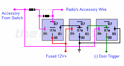
 If you want to prevent 12V+ from feeding back into the accessory circuit or have more than one device on this circuit and do not want all of them to stay powered, you can isolate the device you want to stay powered by cutting the accessory lead going to it and adding two 1 amp diodes and an additional relay as shown below. The first diode near the top left of the diagram is to prevent 12V+ from going back into the accessory circuit. The second diode between terminals 87 and 86 prevents the radio from pulling current through the first diode. If the second diode is not in place, the first diode will become toast. The additional relay is needed to prevent the radio from turning off when the key is in the accessory position and a door is open.
 "
"