Posted: November 20, 2008 at 12:42 PM / IP Logged
Posted: November 20, 2008 at 1:27 PM / IP Logged
Posted: November 22, 2008 at 9:25 PM / IP Logged
Posted: November 25, 2008 at 12:36 PM / IP Logged
Posted: November 26, 2008 at 9:15 PM / IP Logged
Posted: December 03, 2008 at 1:55 AM / IP Logged
Posted: December 03, 2008 at 1:07 PM / IP Logged
Posted: December 13, 2008 at 11:41 AM / IP Logged
Posted: December 14, 2008 at 8:17 AM / IP Logged
Posted: December 14, 2008 at 3:09 PM / IP Logged
 Printable version


| You cannot post new topics in this forum You cannot reply to topics in this forum You cannot delete your posts in this forum You cannot edit your posts in this forum You cannot create polls in this forum You cannot vote in polls in this forum |

| Search the12volt.com |
Follow the12volt.com 
Sunday, January 18, 2026 • Copyright © 1999-2026 the12volt.com, All Rights Reserved • Privacy Policy & Use of Cookies


Sunday, January 18, 2026 • Copyright © 1999-2026 the12volt.com, All Rights Reserved • Privacy Policy & Use of Cookies
Disclaimer:
*All information on this site ( the12volt.com ) is provided "as is" without any warranty of any kind, either expressed or implied, including but not limited to fitness for a particular use. Any user assumes the entire risk as to the accuracy and use of this information. Please
verify all wire colors and diagrams before applying any information.


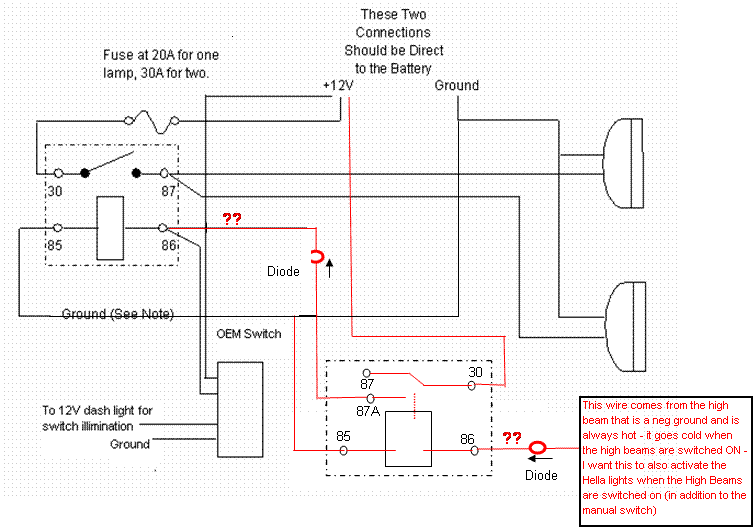
 One thing you could do is to connect an ignition switched line to terminal 85 of your new relay with a diode in series (with the cathode towards the relay). If you connected it to ground the way you show in the diagram, the relay would always be on until you turn your high beams on, not what you want.
Connecting it to a switched ignition line, the relay only energizes when your ignition is on and the high beams switched on. When the ignition is off (and I assume you won't want to turn on your driving lights then), the diode will block any current from backflowing from your high beams.
The rest of the circuit you could use as you drew up (you may want to add a diode between your OEM switch and the relay terminal 86 if your car doesn't like any backfeed from the other relay.) If it doesn't care, you can wire it in directly as you show in your diagram.
Or you could use your added relay to power the aux lights directly, though that means you'll need heavy duty wiring instead of just some thin control wires. I'd just use the relay to control the first one like you did, that'd be the best way.