


bulb out indicator


Posted: November 16, 2011 at 9:37 PM / IP Logged


Posted: November 17, 2011 at 1:13 AM / IP Logged
Posted: November 17, 2011 at 1:38 AM / IP Logged
Posted: November 17, 2011 at 2:09 AM / IP Logged
Posted: November 17, 2011 at 4:04 AM / IP Logged
Posted: November 17, 2011 at 8:00 AM / IP Logged
Posted: November 17, 2011 at 8:37 PM / IP Logged
Posted: November 18, 2011 at 6:26 PM / IP Logged
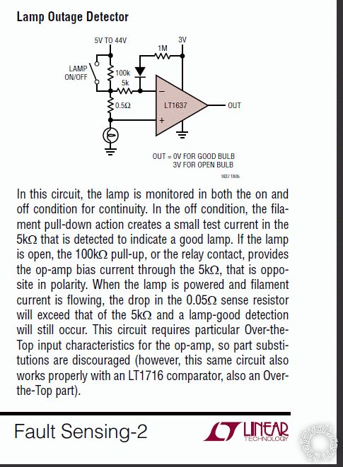 (No Copyright, but thanks to Linear Technology & Tim Regan. IMO a great publication!)
That's just an example using a "high spec" comparator, but it is unusual in that is does includes the switching logic.
Usually it is the lamp switch that supplies the power to the lamp AND the detection circuit. Hence the detection is only active when the lamp should be on - ie, the bad brake-light LED(s) only light when the brake is applied (assuming the brake switch works LOL).
Refer also to Bristolwatch's
(No Copyright, but thanks to Linear Technology & Tim Regan. IMO a great publication!)
That's just an example using a "high spec" comparator, but it is unusual in that is does includes the switching logic.
Usually it is the lamp switch that supplies the power to the lamp AND the detection circuit. Hence the detection is only active when the lamp should be on - ie, the bad brake-light LED(s) only light when the brake is applied (assuming the brake switch works LOL).
Refer also to Bristolwatch's  )
In particular see the "Comparator Operation" section a few screens down. That summarises the input-output relationship, noting that the leftside RV variable resistor (aka pot) is equivalent to an upper and lower resistor as shown for the rightside V-Reference "voltage divider". That was what I meant by "scaling" using 4 resistors - 2 for each input, though one would include a trimpot (variable resistor) for calibration.
Also Rob Paisley is referring to the LM339 and similar Comparators only.
The LM339 is very common and is liked because it uses a single supply, comes in a quad package (4 comparators in one $2 14-pin package), and is an Open-Collector output.
That means you don't have to mess with dual or balanced supplies (ie, +6V, 0V & -6V), and outputs can be directly tied together to make an OR circuit (ie, output LED is on if stop-left is bad OR stop-right is bad OR park-left is bad Or ... etc etc.) - often called Wired-OR logic or circuitry.
[ Open Collector outputs - often called ground switching outputs - are the normal inter-connection technique for digital/computer components, alarm sensors or outputs, ignition systems (eg, points and ignitors), and where systems with different supply voltages require interconnecting. ]
Maybe the type of circuit shown under Bristolwatch/Paisley's "Voltage Window Detector Circuit" (nearly halfway thru the html page) is what you want?
BTW - OpAmps can be used. Comparators are merely OpAmps that are preconfigured as comparators, hence avoiding extra circuitry - and often the requirement or confusion with dual-supply OpAmps.
)
In particular see the "Comparator Operation" section a few screens down. That summarises the input-output relationship, noting that the leftside RV variable resistor (aka pot) is equivalent to an upper and lower resistor as shown for the rightside V-Reference "voltage divider". That was what I meant by "scaling" using 4 resistors - 2 for each input, though one would include a trimpot (variable resistor) for calibration.
Also Rob Paisley is referring to the LM339 and similar Comparators only.
The LM339 is very common and is liked because it uses a single supply, comes in a quad package (4 comparators in one $2 14-pin package), and is an Open-Collector output.
That means you don't have to mess with dual or balanced supplies (ie, +6V, 0V & -6V), and outputs can be directly tied together to make an OR circuit (ie, output LED is on if stop-left is bad OR stop-right is bad OR park-left is bad Or ... etc etc.) - often called Wired-OR logic or circuitry.
[ Open Collector outputs - often called ground switching outputs - are the normal inter-connection technique for digital/computer components, alarm sensors or outputs, ignition systems (eg, points and ignitors), and where systems with different supply voltages require interconnecting. ]
Maybe the type of circuit shown under Bristolwatch/Paisley's "Voltage Window Detector Circuit" (nearly halfway thru the html page) is what you want?
BTW - OpAmps can be used. Comparators are merely OpAmps that are preconfigured as comparators, hence avoiding extra circuitry - and often the requirement or confusion with dual-supply OpAmps.
Posted: November 21, 2011 at 12:56 AM / IP Logged
Posted: November 22, 2011 at 1:19 AM / IP Logged
 Printable version
| You cannot post new topics in this forum You cannot reply to topics in this forum You cannot delete your posts in this forum You cannot edit your posts in this forum You cannot create polls in this forum You cannot vote in polls in this forum |

| Search the12volt.com |
Follow the12volt.com 
Sunday, March 22, 2026 • Copyright © 1999-2026 the12volt.com, All Rights Reserved • Privacy Policy & Use of Cookies

Sunday, March 22, 2026 • Copyright © 1999-2026 the12volt.com, All Rights Reserved • Privacy Policy & Use of Cookies
Disclaimer:
*All information on this site ( the12volt.com ) is provided "as is" without any warranty of any kind, either expressed or implied, including but not limited to fitness for a particular use. Any user assumes the entire risk as to the accuracy and use of this information. Please
verify all wire colors and diagrams before applying any information.
