


Express dball 2 and Viper 5706v Wiring
Home /
the12volt's Install Bay /
Car Security and Convenience / Express dball 2 and Viper 5706v Wiring ( Topic Closed)


Posted: February 28, 2014 at 12:02 AM / IP Logged
 and the viper 5704

Posted: February 28, 2014 at 6:40 PM / IP Logged

Posted: February 28, 2014 at 7:12 PM / IP Logged
Posted: March 01, 2014 at 8:25 AM / IP Logged
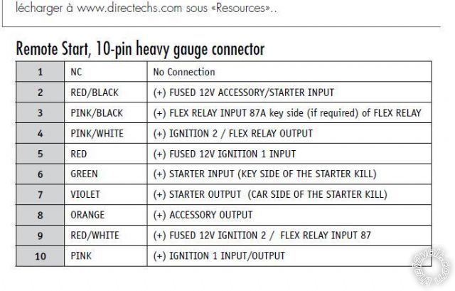 Here is what i am thinking of doing:
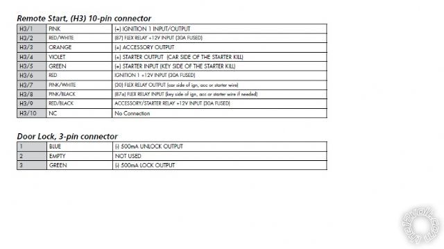
1 NC No Connection
NOT USED
2 RED / BLACK (+) FUSED 12V ACCESSORY/STARTER INPUT;
NOT USED?
or Do i need to connect this to Accessory wire ( WHITE(+) and orange)? This does not make sense? as one is input and output together.
3 PINK/BLACK (+) FLEX RELAY INPUT 87A key side (if required) of FLEX RELAY;
NOT USED
4 PINK/WHITE (+) IGNITION 2 / FLEX RELAY OUTPUT;
This is for the Ignition 2 wire (PINK (+).
( I know i can switch this to Accessory 2 or Starter 2 in programming , but for now I leave it as Ignition 2, so I don't have to put a relay, but maybe then I need to put a relay for starter 2.)
5 RED (+) FUSED 12V IGNITION 1 INPUT;
NOT USED?
or do i need to join with Ignition 1 wire(YEllOW (+)( this does not make sense where you have this coming and the 10 PINK (+) wire coming together. Anyways I don't think it is needed.
6 GREEN (+) STARTER INPUT (KEY SIDE OF THE STARTER KILL);
(STARTER 1 and 2 wires)(YELLOW (+) and PINK (+)) cut and join together key side wires to this green wire. (Basically 2 wires joined together to this green wire) Again I don't know if I need to use a relay for the 2nd starter wire?
7 VIOLET (+) STARTER OUTPUT (CAR SIDE OF THE STARTER KILL);
(STARTER 1 and 2 wires)(YELLOW (+) and PINK (+)) cut and join together car side wire to this violet wire. I don't know if this is correct; I have read that I should use a relay for the 2nd starter wire; someone explain how if so needed.
8 ORANGE (+) ACCESSORY OUTPUT;
WHITE (+) join this Orange
9 RED / WHITE (+) FUSED 12V IGNITION 2 / FLEX RELAY INPUT 87;
NOT USED
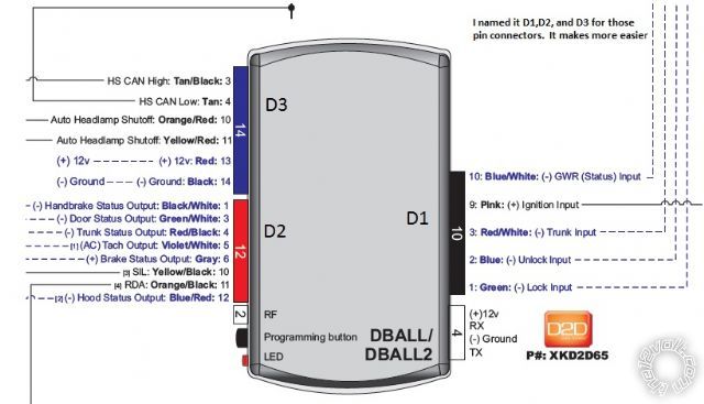
10 PINK (+) IGNITION 1 INPUT/OUTPUT ;
Connect to Ignition 1 wire; BLUE (+)
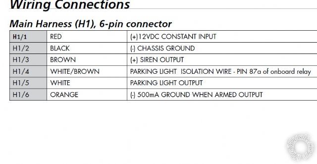
Overall I am getting confused in how the 2 ignition wires need to go and the 2 starter wires. If someone can clarify that would help me a lot. I am going to use D2D, and for the idatalink I dont have to connect that may wires. The 12 volt input constant on 6pin main harness has 15 amp fuse, while the rest of fused (3 wires) on the 10pin harness have 20 amp fuse.
Here is what i am thinking of doing:
1 NC No Connection
NOT USED
2 RED / BLACK (+) FUSED 12V ACCESSORY/STARTER INPUT;
NOT USED?
or Do i need to connect this to Accessory wire ( WHITE(+) and orange)? This does not make sense? as one is input and output together.
3 PINK/BLACK (+) FLEX RELAY INPUT 87A key side (if required) of FLEX RELAY;
NOT USED
4 PINK/WHITE (+) IGNITION 2 / FLEX RELAY OUTPUT;
This is for the Ignition 2 wire (PINK (+).
( I know i can switch this to Accessory 2 or Starter 2 in programming , but for now I leave it as Ignition 2, so I don't have to put a relay, but maybe then I need to put a relay for starter 2.)
5 RED (+) FUSED 12V IGNITION 1 INPUT;
NOT USED?
or do i need to join with Ignition 1 wire(YEllOW (+)( this does not make sense where you have this coming and the 10 PINK (+) wire coming together. Anyways I don't think it is needed.
6 GREEN (+) STARTER INPUT (KEY SIDE OF THE STARTER KILL);
(STARTER 1 and 2 wires)(YELLOW (+) and PINK (+)) cut and join together key side wires to this green wire. (Basically 2 wires joined together to this green wire) Again I don't know if I need to use a relay for the 2nd starter wire?
7 VIOLET (+) STARTER OUTPUT (CAR SIDE OF THE STARTER KILL);
(STARTER 1 and 2 wires)(YELLOW (+) and PINK (+)) cut and join together car side wire to this violet wire. I don't know if this is correct; I have read that I should use a relay for the 2nd starter wire; someone explain how if so needed.
8 ORANGE (+) ACCESSORY OUTPUT;
WHITE (+) join this Orange
9 RED / WHITE (+) FUSED 12V IGNITION 2 / FLEX RELAY INPUT 87;
NOT USED
10 PINK (+) IGNITION 1 INPUT/OUTPUT ;
Connect to Ignition 1 wire; BLUE (+)
Overall I am getting confused in how the 2 ignition wires need to go and the 2 starter wires. If someone can clarify that would help me a lot. I am going to use D2D, and for the idatalink I dont have to connect that may wires. The 12 volt input constant on 6pin main harness has 15 amp fuse, while the rest of fused (3 wires) on the 10pin harness have 20 amp fuse.Posted: March 01, 2014 at 9:01 AM / IP Logged
Posted: March 01, 2014 at 9:31 AM / IP Logged
Posted: March 01, 2014 at 10:33 AM / IP Logged
Posted: March 01, 2014 at 11:30 AM / IP Logged
Posted: March 01, 2014 at 12:07 PM / IP Logged
Posted: March 01, 2014 at 12:21 PM / IP Logged
 Printable version
| You cannot post new topics in this forum You cannot reply to topics in this forum You cannot delete your posts in this forum You cannot edit your posts in this forum You cannot create polls in this forum You cannot vote in polls in this forum |

| Search the12volt.com |
Follow the12volt.com 
Thursday, April 9, 2026 • Copyright © 1999-2026 the12volt.com, All Rights Reserved • Privacy Policy & Use of Cookies

Thursday, April 9, 2026 • Copyright © 1999-2026 the12volt.com, All Rights Reserved • Privacy Policy & Use of Cookies
Disclaimer:
*All information on this site ( the12volt.com ) is provided "as is" without any warranty of any kind, either expressed or implied, including but not limited to fitness for a particular use. Any user assumes the entire risk as to the accuracy and use of this information. Please
verify all wire colors and diagrams before applying any information.
