


 And will be connected to the main ground plane on the bottom of the board. I don't have any newer units to look at in case the are using a SMD package or not in the newer units.
IF your going to test it disconnect it from all wires and then open it up by removing the 4 screws on the bottom corners.
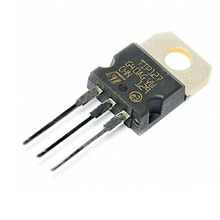
You can check it like a diode for continuity. The legs connected to ground and GWA Should test Open or high resistance with probes both ways. And the Non ground pin should only test 1 way to each of the Ground and GWA legs.
And will be connected to the main ground plane on the bottom of the board. I don't have any newer units to look at in case the are using a SMD package or not in the newer units.
IF your going to test it disconnect it from all wires and then open it up by removing the 4 screws on the bottom corners.
You can check it like a diode for continuity. The legs connected to ground and GWA Should test Open or high resistance with probes both ways. And the Non ground pin should only test 1 way to each of the Ground and GWA legs.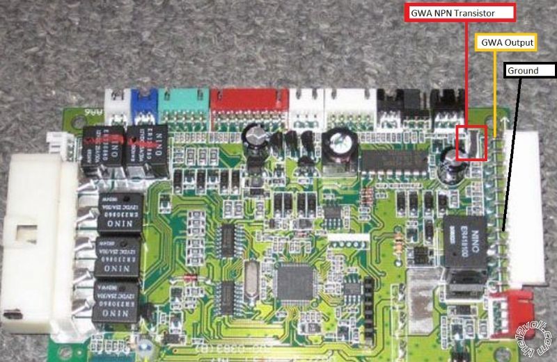
If you wish to post a reply to this topic, you must first login.
If you are not already registered, you must first register.
 Printable version


| You cannot post new topics in this forum You cannot reply to topics in this forum You cannot delete your posts in this forum You cannot edit your posts in this forum You cannot create polls in this forum You cannot vote in polls in this forum |

| Search the12volt.com |
Follow the12volt.com 
Monday, April 6, 2026 • Copyright © 1999-2026 the12volt.com, All Rights Reserved • Privacy Policy & Use of Cookies

Monday, April 6, 2026 • Copyright © 1999-2026 the12volt.com, All Rights Reserved • Privacy Policy & Use of Cookies
Disclaimer:
*All information on this site ( the12volt.com ) is provided "as is" without any warranty of any kind, either expressed or implied, including but not limited to fitness for a particular use. Any user assumes the entire risk as to the accuracy and use of this information. Please
verify all wire colors and diagrams before applying any information.
