Here's my info (THANKS to the member who posted the spreadsheet) can someone please check for errors?
Vehicle Information: 2015 HONDA ACCORD SPORT, 4 CYLINDER, AUTOMATIC TRANSMISSION, STANDARD KEY
Alarm / Remote Start Unit: COMPUSTAR 7000AS/Pro T11 2-WAY REMOTE
Bypass Module: IDATALINK BLADE-AL(DL)-HA6
Alarm / Remote Start / Bypass Unit Vehicle
Connection Connection
Color Description Color Polarity Location:
High Current Ignition Harness (CN1)
12V Constant (pin 1) Red Constant 12V "power wire" White (50 AMP) (+) Green Ignition connector above upper fuse box, or main ignition connector under steering
column
12V Selectable (Default Parking Light, pin 2) GREEN / WHITE Programmable output (+) Red (+) See Above
12V Constant (pin 3) RED / White Accessory and starter output White (50 AMP) (+) See Above
12V Selectable (Default Accessory (pin 4) White Accessory/HVAC blower motor Orange (+) See Above
12V Selectable (Default ignition 2, pin 5) Blue 2nd ign, 2nd acc, or parking lt out N/A (+)
12V Starter (pin 6) Yellow Starter 12V (+) output Blue (+) See Above
12V Ignition (pin 7) Green Ignition 12V (+) output/input Green (+) See Above
Ground Black Ground (-) To chassis ground (-) Vehicle chassis ground
Blade Connector (CN4)
Ignition connector side (pin 20) WHITE/ Black Brown (+) Transponder plug (pin 2) connector side
Ignition vehicle side (pin 10) WHITE/ Red Brown (+) Transponder plug (pin 2) vehicle side
CanH (pin 6) BROWN / Red Pink DATA Transponder plug (pin 4)
CanL (pin 16) BROWN / Yellow Blue DATA Transponder plug (pin 3)
Key Data ORANGE / Black Grey DATA Transponder plug (pin 6)
Ignition Input Pink Ties into WHITE/ Red on vehicle ignition side Brown (+) Transponder plug (pin 2) or ties into the WHITE/ Red wire from Blade Connector
Programmable Output Channel (CN5)
So far nada....
I also have a few questions:
1. I would like to wire the remote's AUX 1 to the window defroster... what wires can I use and do the brains need to be programmed? I know where to access the defroster wire and I have a weblink account and USB connector, but do not own an OP500...
2. I've read that the ground to chassis limits the RF signal range of the remote. Is there a better place to ground the system? Any experience with this situation?
3. Is it possible to wire a windows up feature as an aux? If so how hard and labor intensive is it?
4. I'd be wiring both the siren, and thermistor. Where is the best place to, and how would you mount them?
THANKS again for all your help!


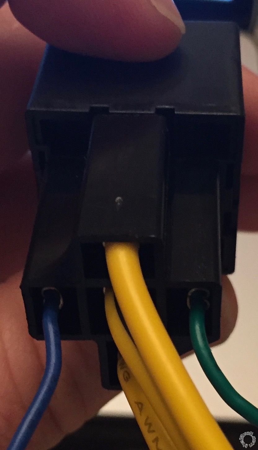
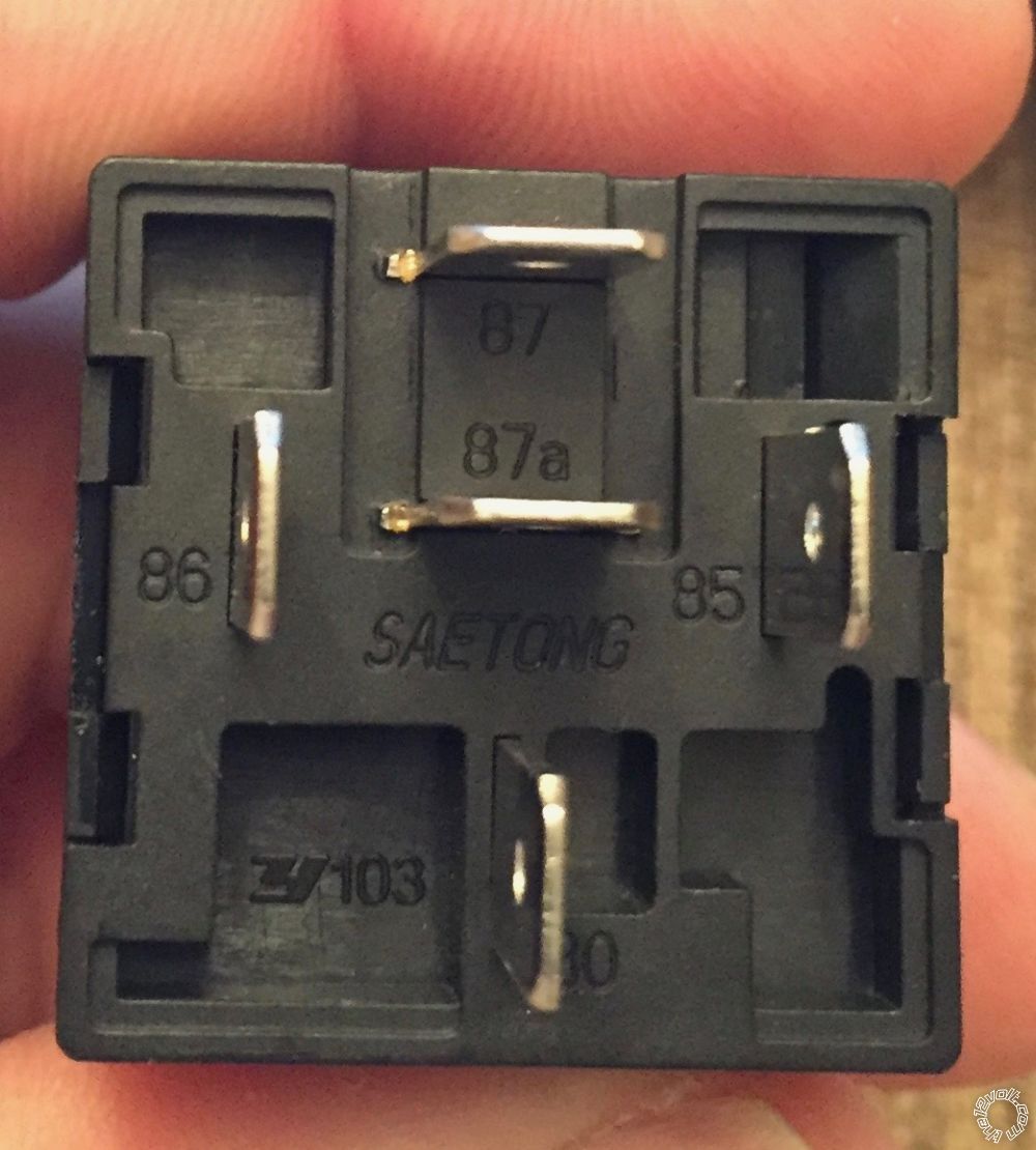
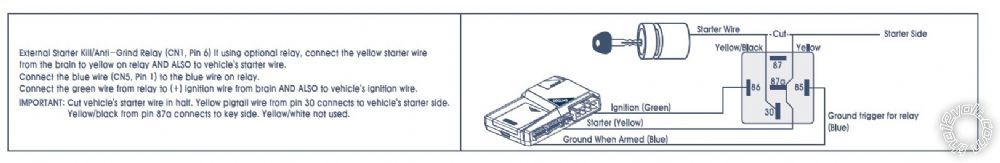 As you can see it shows 86 as the ignition/green wire and 85 as the ground trigger for relay/GWA blue wire from the RS. HOWEVER, when I compare the actual relay that was provided it appears these two have been switched. Am I imagining things? It seems that this flys in the face of conventional wisdom; however, I did just complete a 13 hr flight and probably shouldn't be tooling around with this stuff right now...
 Any assistance is greatly appreciated...
 I would like to add the ability to vent my windows using the AUX 1 output (it can provide a 250 mA (-) signal for 0.5 seconds or is programmable up to 99 seconds, but has no "validity" mode like other systems). The end goal is to enable AUX 1 to vent the windows at almost any time, just not during start up. I believe that at a minimum I'll need to borrow the GWA from the 7000AS (wire I used in the anti-grind relay), add some diodes, and if I'm not mistaken it may be best to add another relay. How would you wire all this to achieve the desired effects?
Thanks!
I would like to add the ability to vent my windows using the AUX 1 output (it can provide a 250 mA (-) signal for 0.5 seconds or is programmable up to 99 seconds, but has no "validity" mode like other systems). The end goal is to enable AUX 1 to vent the windows at almost any time, just not during start up. I believe that at a minimum I'll need to borrow the GWA from the 7000AS (wire I used in the anti-grind relay), add some diodes, and if I'm not mistaken it may be best to add another relay. How would you wire all this to achieve the desired effects?
Thanks!


 Printable version


