


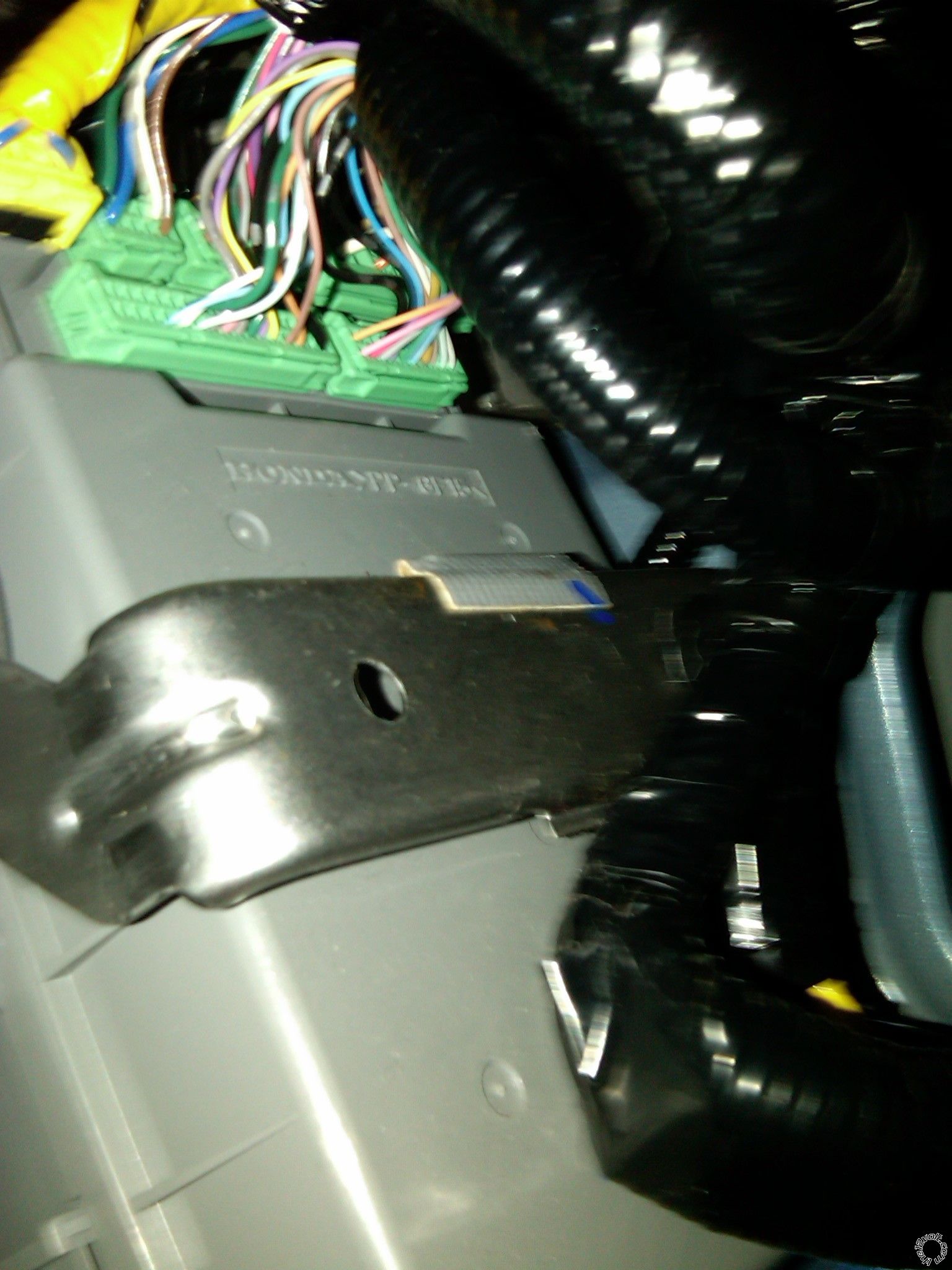
 Here is a picture of the connector that I think you are talking about. You can see the orange wire next to the brown wire. I don't have this wire
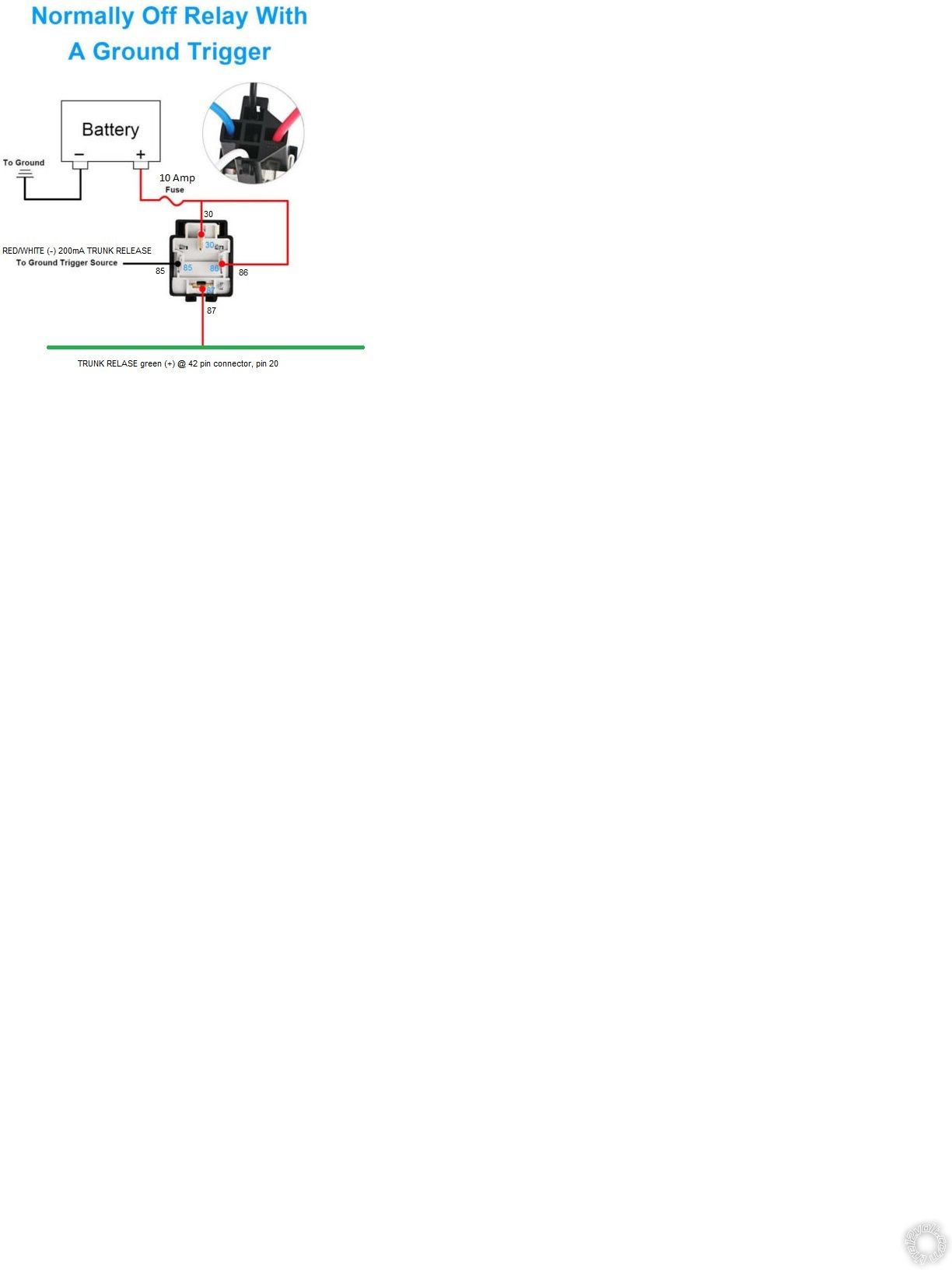 You supply the relay with a +12V constant power source fused to 10 Amps. This power input goes to Pin 30 and Pin 86. Pin 86 is one side of the relays internal coil and by convention should be (+).
The Vipers Red/White (-) 200mA TRUNK RELASE output goes to Pin 85. This is the other side of the internal coil. When the Viper gets the Trunk Release command from the Viper remote it will output
a 1 second (-) signal that will actuate the relay. With the coil energized, it will make an internal connection between Pin 87 and Pin 30. This allows the +12V at Pin 30 to exit Pin 87. Pin 87
is connected to the Civics TRUNK RELASE green (+) @ 42 pin connector, pin 20. The trunk pops open.
You supply the relay with a +12V constant power source fused to 10 Amps. This power input goes to Pin 30 and Pin 86. Pin 86 is one side of the relays internal coil and by convention should be (+).
The Vipers Red/White (-) 200mA TRUNK RELASE output goes to Pin 85. This is the other side of the internal coil. When the Viper gets the Trunk Release command from the Viper remote it will output
a 1 second (-) signal that will actuate the relay. With the coil energized, it will make an internal connection between Pin 87 and Pin 30. This allows the +12V at Pin 30 to exit Pin 87. Pin 87
is connected to the Civics TRUNK RELASE green (+) @ 42 pin connector, pin 20. The trunk pops open.If you wish to post a reply to this topic, you must first login.
If you are not already registered, you must first register.
 Printable version


| You cannot post new topics in this forum You cannot reply to topics in this forum You cannot delete your posts in this forum You cannot edit your posts in this forum You cannot create polls in this forum You cannot vote in polls in this forum |

| Search the12volt.com |
Follow the12volt.com 
Friday, May 15, 2026 • Copyright © 1999-2026 the12volt.com, All Rights Reserved • Privacy Policy & Use of Cookies

Friday, May 15, 2026 • Copyright © 1999-2026 the12volt.com, All Rights Reserved • Privacy Policy & Use of Cookies
Disclaimer:
*All information on this site ( the12volt.com ) is provided "as is" without any warranty of any kind, either expressed or implied, including but not limited to fitness for a particular use. Any user assumes the entire risk as to the accuracy and use of this information. Please
verify all wire colors and diagrams before applying any information.
