the12volt.com spacer
icon

Latched relay?


Post ReplyPost New Topic
< Prev Topic Next Topic >
master5 
Silver - Posts: 1,123
Silver spacespace
Joined: October 10, 2006
Location: United States
Posted: December 01, 2006 at 10:08 PM / IP Logged  

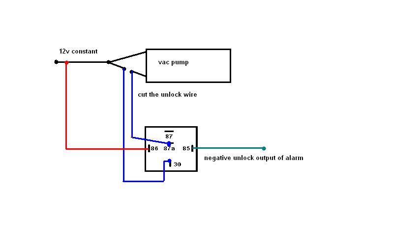
Oh wait....lol....now I get it....ok..your diagram shows rest at 12v+..... N/C for lock..N/O for unlock...wire it like this...Do we have a winner???

Latched relay? - Page 2 -- posted image.

master5 
Silver - Posts: 1,123
Silver spacespace
Joined: October 10, 2006
Location: United States
Posted: December 01, 2006 at 10:23 PM / IP Logged  
If that doesn't work..put the wire that is on 87a to 87..Its been like 10 years since I have done this..but I know it will work..you just need to get the relay to simulate what the switch does...the older benzes that I was confusing this system with requires the extended pulse if doing the locks at the pump. Since you are using the factory switch at the door via an electronic actuator..and your problem seems to be it doesn't fully engage the switch for unlock...this will work. Sorry for all the confusion..you gotta laugh.
master5 
Silver - Posts: 1,123
Silver spacespace
Joined: October 10, 2006
Location: United States
Posted: December 01, 2006 at 10:30 PM / IP Logged  
Wizard...man you are the diagram wizard..amazing.The only thing is..and I should have stated this earlier..is if it did require the extended pulse..it would only need about 3 seconds max...just long enough for the pump to cycle long enough to lock and unlock..30 seconds is way overkill. But since in this case we are at the switch in the door that controls the module ..we do not need the delay.
hotwaterwizard 
Silver - Posts: 1,350
Silver spacespace
Joined: December 11, 2003
Location: California, United States
Posted: December 01, 2006 at 11:26 PM / IP Logged  

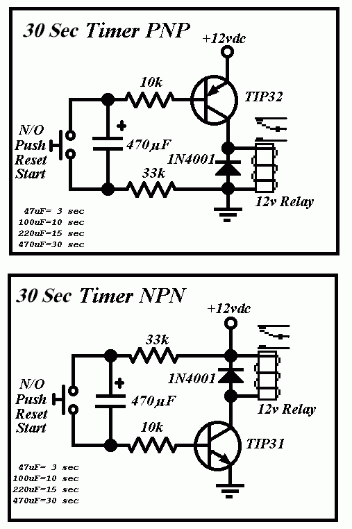
Did you look at the other Diagram?

Just use a 47uF Capacitor instead of a 470uF.

John DeRosa (Hotwaterwizard)
Stockton California
When in doubt, try it out !
hotwaterwizard 
Silver - Posts: 1,350
Silver spacespace
Joined: December 11, 2003
Location: California, United States
Posted: December 01, 2006 at 11:31 PM / IP Logged  
Latched relay? - Page 2 -- posted image.
John DeRosa (Hotwaterwizard)
Stockton California
When in doubt, try it out !
KPierson 
Platinum - Posts: 3,527
Platinum spaceThis member consistently provides reliable informationspace
Joined: April 14, 2005
Location: Ohio, United States
Posted: December 02, 2006 at 12:12 AM / IP Logged  

Are you sure that diagram will work?  Where is your voltage differential that charges the cap?  Looks like both sides of it will go to ground.

Kevin Pierson
hotwaterwizard 
Silver - Posts: 1,350
Silver spacespace
Joined: December 11, 2003
Location: California, United States
Posted: December 02, 2006 at 12:26 AM / IP Logged  

Yes this one works. The Transistor provides the voltage until saturation is achieved.

The capacitor charges at a RC time set by the components.

The capacitor starts charging when you short it out and release.

When the capacitor  gets to a full charge it turns off the second relay .

When in doubt, try it out !       When in doubt, try it out !

John DeRosa (Hotwaterwizard)
Stockton California
When in doubt, try it out !
KPierson 
Platinum - Posts: 3,527
Platinum spaceThis member consistently provides reliable informationspace
Joined: April 14, 2005
Location: Ohio, United States
Posted: December 02, 2006 at 12:31 AM / IP Logged  

Where is the voltage supplied from that charges the cap?  From the top of the emitter back through the base?  Also, how is the cap discharging going to keep a PNP transistor biased? 

Kevin Pierson
hotwaterwizard 
Silver - Posts: 1,350
Silver spacespace
Joined: December 11, 2003
Location: California, United States
Posted: December 02, 2006 at 12:34 AM / IP Logged  

Latched relay? - Page 2 -- posted image.

This is the Original circuit that I modified. Trust me it works.

John DeRosa (Hotwaterwizard)
Stockton California
When in doubt, try it out !
KPierson 
Platinum - Posts: 3,527
Platinum spaceThis member consistently provides reliable informationspace
Joined: April 14, 2005
Location: Ohio, United States
Posted: December 02, 2006 at 1:03 AM / IP Logged  

OK, a little time with my 'scope and I see now.

I built the NPN version, using a 30K resistor, a 10K resistor, a 2n3904, and a 68uF electrolytic cap.

The two resistors in series form a voltage divider, making the base of the transistor more negative then the power supply.  When you short out the cap it discharges, and as the cap charges back up it allows voltage to pass through it.  Once the cap is full, it 'opens' and no more current flows.

I never would have thought to do it that way.

Hmmm... you know you are getting older when you don't have anything better to do at 2AM on a Friday night then learn how a new circuit works......

Kevin Pierson
Page of 4

  Printable version Printable version Post ReplyPost New Topic
You cannot post new topics in this forum
You cannot reply to topics in this forum
You cannot delete your posts in this forum
You cannot edit your posts in this forum
You cannot create polls in this forum
You cannot vote in polls in this forum

  •  
Search the12volt.com
Follow the12volt.com Follow the12volt.com on Facebook
Thursday, July 3, 2025 • Copyright © 1999-2025 the12volt.com, All Rights Reserved Privacy Policy & Use of Cookies
Disclaimer: *All information on this site ( the12volt.com ) is provided "as is" without any warranty of any kind, either expressed or implied, including but not limited to fitness for a particular use. Any user assumes the entire risk as to the accuracy and use of this information. Please verify all wire colors and diagrams before applying any information.

Secured by Sectigo
the12volt.com spacer
Support the12volt.com
Top
the12volt.com spacer