


viper 5902 + dball in hyundai 2012
Home /
the12volt's Install Bay /
Car Security and Convenience / viper 5902 + dball in hyundai 2012 ( Topic Closed)


Posted: February 20, 2013 at 4:21 PM / IP Logged

Posted: February 21, 2013 at 8:05 AM / IP Logged


Posted: February 21, 2013 at 10:52 AM / IP Logged
Posted: February 22, 2013 at 6:31 PM / IP Logged
Posted: February 22, 2013 at 9:05 PM / IP Logged
Posted: February 23, 2013 at 12:51 AM / IP Logged
Posted: February 23, 2013 at 4:32 AM / IP Logged
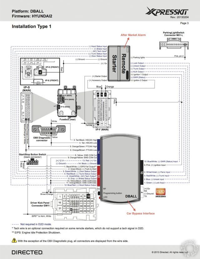
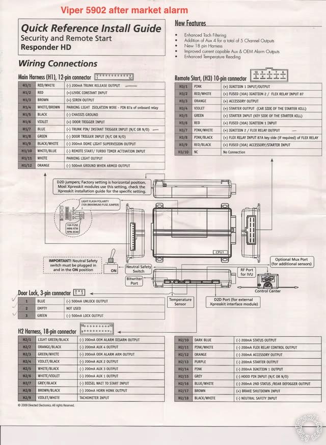 DBALL Viper 5902
Blue Harn. Pin 13 +12V Red to same +12V on I/P-D Pin 2 in smart junction box
Blue Harn. Pin 14 - ground to chasis or connect with ground of Viper 5902 H1/5 Black
Red Harn. Pin 3 GREEN / WHITE to 5902 CPU H1/8 Green (-) Door Trigger Input
Red Harn. Pin 4 RED / Black to 5902 CPU H1/7 Blue (-)Trunk Pin/Instant Trigger Input
Red Harn. Pin 5 Violet/White to 5902 CPU H2/9 Violet/White Tachometer Input
Red Harn. Pin 6 Grey to 5902 CPU H2/17 Brown (+) Brake Shutdown Input
Red Harn. Pin 12 Blue/Red to 5902 CPU H2/15 Grey (-) Hood Pin Input
Black Harn. Pin 1 Green to 5902 CPU Door Lock Harn. Pin 3 Green (-) 500mA Lock Output
Black Harn. Pin 2 Blue to 5902 CPU Door Lock Harn. Pin 1 Blue (-) 500mA Unlock Output
Black Harn. Pin 3 RED / White to 5902 CPU H1/1 RED / White (-) 200mA Trunk Release Output
Black Harn. Pin 4 WHITE/ Violet to 5902 CPU ?????? (I don't know to which wire)
Black Harn. Pin 10 Blue/White to 5902 CPU ?????? (I don't Know what is GWR and to which wire)
Black Harn. Pin 9 Pink Soldered to 5902 CPU H3/1 Pink (+) Ignition 1 Input/Output so
cable will be soldered I/P-F Pin 27 in smart junction box
For this wire connection will I need any diodes or relays or fuse?
DBALL Viper 5902
Blue Harn. Pin 13 +12V Red to same +12V on I/P-D Pin 2 in smart junction box
Blue Harn. Pin 14 - ground to chasis or connect with ground of Viper 5902 H1/5 Black
Red Harn. Pin 3 GREEN / WHITE to 5902 CPU H1/8 Green (-) Door Trigger Input
Red Harn. Pin 4 RED / Black to 5902 CPU H1/7 Blue (-)Trunk Pin/Instant Trigger Input
Red Harn. Pin 5 Violet/White to 5902 CPU H2/9 Violet/White Tachometer Input
Red Harn. Pin 6 Grey to 5902 CPU H2/17 Brown (+) Brake Shutdown Input
Red Harn. Pin 12 Blue/Red to 5902 CPU H2/15 Grey (-) Hood Pin Input
Black Harn. Pin 1 Green to 5902 CPU Door Lock Harn. Pin 3 Green (-) 500mA Lock Output
Black Harn. Pin 2 Blue to 5902 CPU Door Lock Harn. Pin 1 Blue (-) 500mA Unlock Output
Black Harn. Pin 3 RED / White to 5902 CPU H1/1 RED / White (-) 200mA Trunk Release Output
Black Harn. Pin 4 WHITE/ Violet to 5902 CPU ?????? (I don't know to which wire)
Black Harn. Pin 10 Blue/White to 5902 CPU ?????? (I don't Know what is GWR and to which wire)
Black Harn. Pin 9 Pink Soldered to 5902 CPU H3/1 Pink (+) Ignition 1 Input/Output so
cable will be soldered I/P-F Pin 27 in smart junction box
For this wire connection will I need any diodes or relays or fuse?Posted: February 23, 2013 at 4:54 AM / IP Logged
Posted: February 23, 2013 at 7:09 AM / IP Logged
Posted: February 23, 2013 at 7:12 AM / IP Logged
 Printable version
| You cannot post new topics in this forum You cannot reply to topics in this forum You cannot delete your posts in this forum You cannot edit your posts in this forum You cannot create polls in this forum You cannot vote in polls in this forum |

| Search the12volt.com |
Follow the12volt.com 
Saturday, May 16, 2026 • Copyright © 1999-2026 the12volt.com, All Rights Reserved • Privacy Policy & Use of Cookies

Saturday, May 16, 2026 • Copyright © 1999-2026 the12volt.com, All Rights Reserved • Privacy Policy & Use of Cookies
Disclaimer:
*All information on this site ( the12volt.com ) is provided "as is" without any warranty of any kind, either expressed or implied, including but not limited to fitness for a particular use. Any user assumes the entire risk as to the accuracy and use of this information. Please
verify all wire colors and diagrams before applying any information.
