


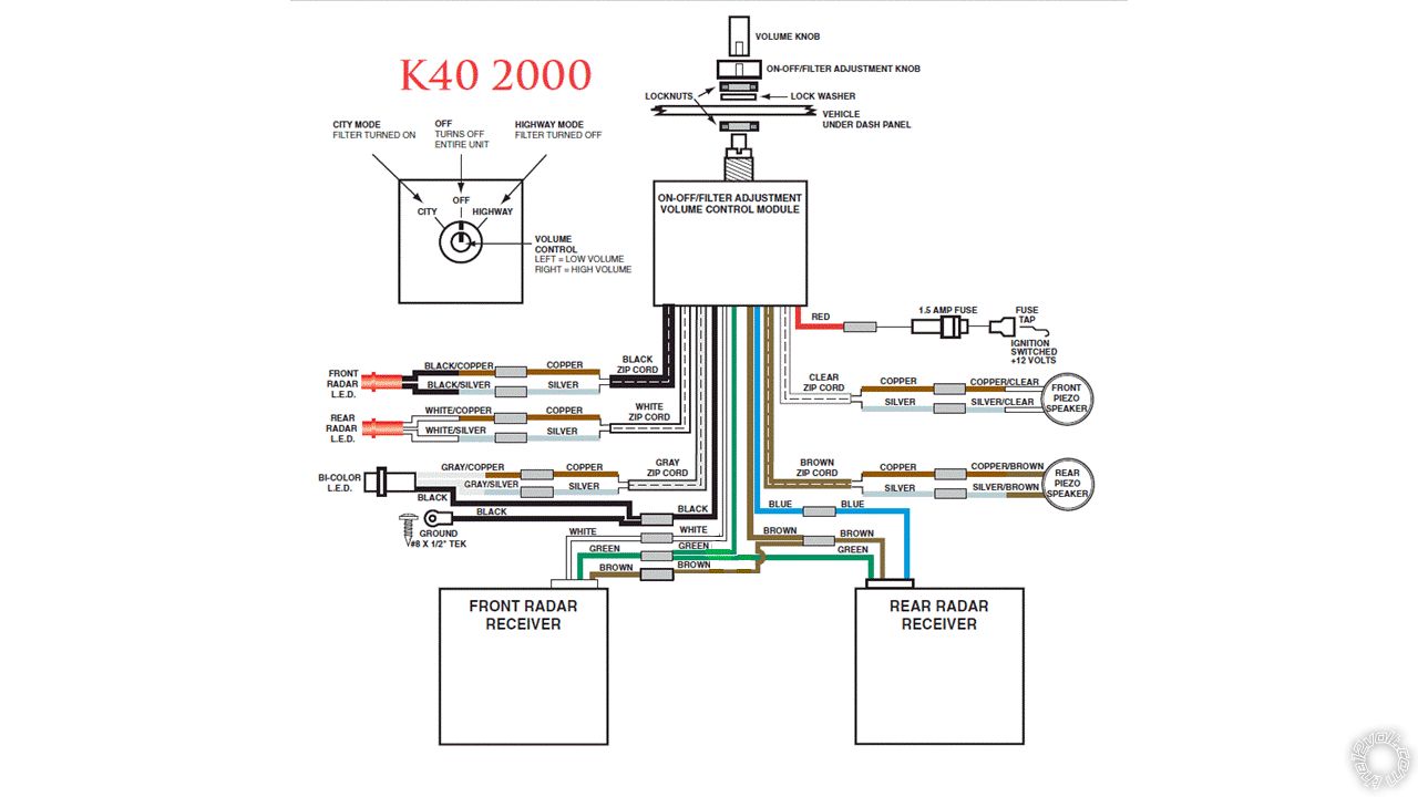
 Looking at the diagram I saw that there was a inline fuse. Ok I thought, that should be an easy fix. Well I was wrong for a very strange reason. There was a capacitor in the circuit instead of a fuse. I've modified the original diagram to show the current circuit here.
 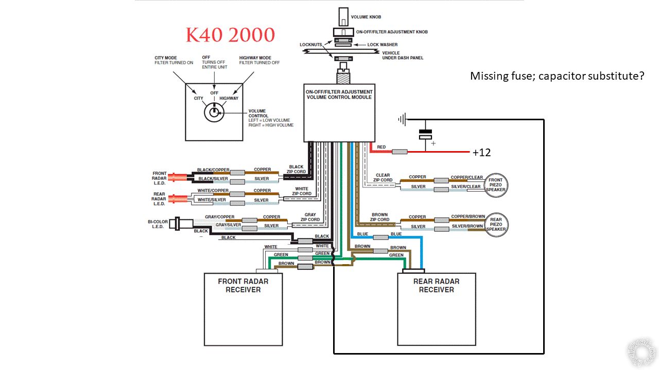 So, since I know very little about electronics, I thought it would be prudent of me to see if I could find out why this was done before I ripped the capacitor out and put the fuse back in. Can anyone out there explain why this was done?
Thanks, all replies are appreciated.
So, since I know very little about electronics, I thought it would be prudent of me to see if I could find out why this was done before I ripped the capacitor out and put the fuse back in. Can anyone out there explain why this was done?
Thanks, all replies are appreciated.
If you wish to post a reply to this topic, you must first login.
If you are not already registered, you must first register.
 Printable version


| You cannot post new topics in this forum You cannot reply to topics in this forum You cannot delete your posts in this forum You cannot edit your posts in this forum You cannot create polls in this forum You cannot vote in polls in this forum |

| Search the12volt.com |
Follow the12volt.com 
Tuesday, May 12, 2026 • Copyright © 1999-2026 the12volt.com, All Rights Reserved • Privacy Policy & Use of Cookies

Tuesday, May 12, 2026 • Copyright © 1999-2026 the12volt.com, All Rights Reserved • Privacy Policy & Use of Cookies
Disclaimer:
*All information on this site ( the12volt.com ) is provided "as is" without any warranty of any kind, either expressed or implied, including but not limited to fitness for a particular use. Any user assumes the entire risk as to the accuracy and use of this information. Please
verify all wire colors and diagrams before applying any information.
