


2007-2012 Silverado, Bench Prep, Remote Start Pictorial
Home /
the12volt's Install Bay /
Car Security and Convenience - Alarm/Remote Start Pictorials / 2007-2012 Silverado, Bench Prep, Remote Start Pictorial ( Topic Closed)


Posted: February 24, 2013 at 5:27 PM / IP Logged
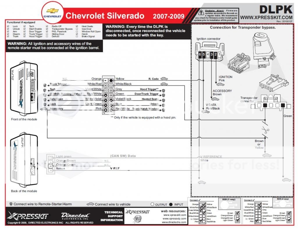 First the DLPK printout which shows all the connections we will have to make at the ignition harness. This covers all connections except a +12 volt, ground, parking light, and brake wire.
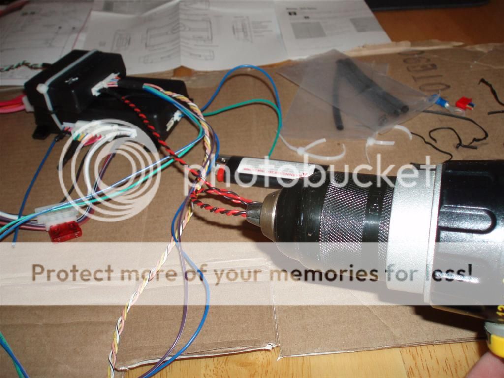
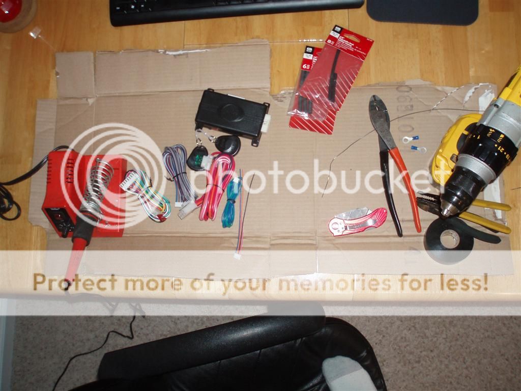 Tools I use for bench prep and for install. A cordless drill, wire cutters, strippers, crimper, electrical tape, soldering iron, solder, heat shrink tubing.
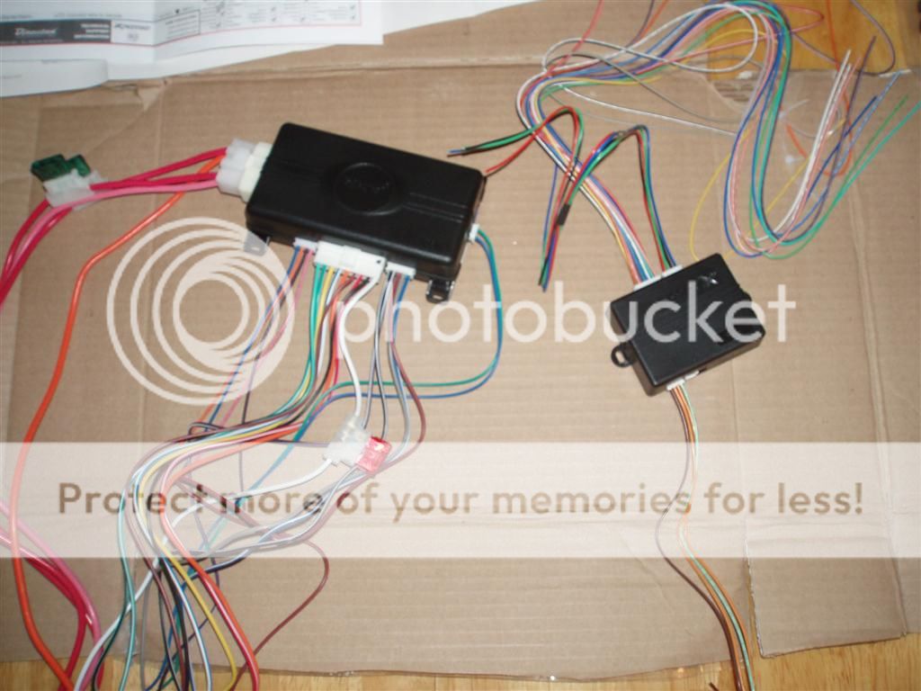 Avital & DLPK laying out with all harness opened up and connected. At this point many will be intimidated by all the wires but dont worry we wont use many of them.
The wires we will use for this are as follows, all others are cut back and not used.
Avital & DLPK laying out with all harness opened up and connected. At this point many will be intimidated by all the wires but dont worry we wont use many of them.
The wires we will use for this are as follows, all others are cut back and not used.
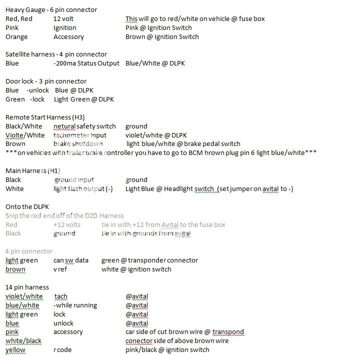 The above are the only wires we will be using, all others can be cut back and have heat shrink put over them. Make your connections between the avital and the dlpk and then group your wires that are going to ignition switch and transponder connector and spin them together in your drill.
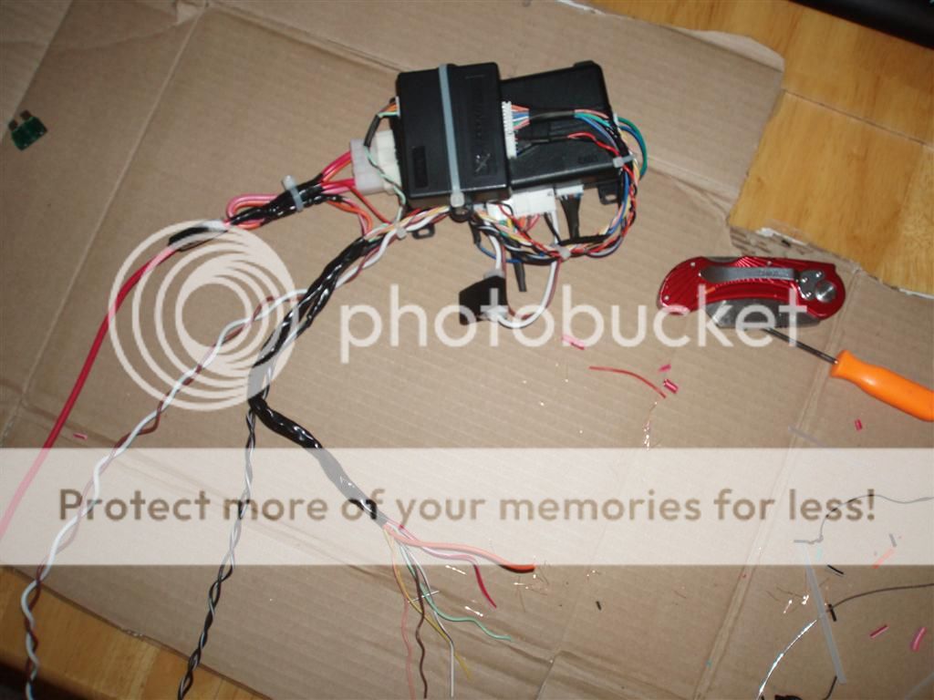
 In this pictures you can see I have strapped the dlpk to avial and cut most of the unneeded wires away. I have heat shrunk over them and I am starting to spin wires together with the drill.
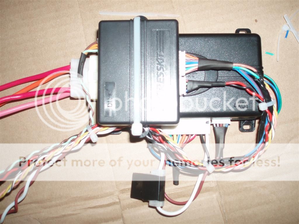 I now have made all connections between avital and dlpk. All connectinos are soldered and taped or heat shrinked. Most wires have been spun up in the drill and everything is zip tied together. Dont forget to tape the fuse into the fuse holder as well.
 At this point we now have taken the black and red from dlpk and spliced them in with the +12 and ground from the avital. Since this unit will pull very little current as it is just picking relays not really powering anything I cut the one +12 volt wire from the avital just before the fuse holder and splice it and the red wire from dlpk into the other +12 volt wire after the fuse holder. I also downfuse the unit as well to 10 amps.
Also I take the Pink and Purple heavy gauge wires and splice them into a 16ga wire since heavy gauge isnt needed for this vehicle and it will make it easier to run. I then tape up my main bundle that will run up into the steering column. This bundle has Ignition, Accessory, R code, Data, V Ref, and the 2 wires that go to accessory feed at transponder. We then have the ground/nss wire that will be grounded on a factory stud, brake shutdown, parking light wire, and +12 volt feed. Looks much less intimidating then the early picture.
Part 2 will cover the actual installation into a 2012 Silverado
At this point we now have taken the black and red from dlpk and spliced them in with the +12 and ground from the avital. Since this unit will pull very little current as it is just picking relays not really powering anything I cut the one +12 volt wire from the avital just before the fuse holder and splice it and the red wire from dlpk into the other +12 volt wire after the fuse holder. I also downfuse the unit as well to 10 amps.
Also I take the Pink and Purple heavy gauge wires and splice them into a 16ga wire since heavy gauge isnt needed for this vehicle and it will make it easier to run. I then tape up my main bundle that will run up into the steering column. This bundle has Ignition, Accessory, R code, Data, V Ref, and the 2 wires that go to accessory feed at transponder. We then have the ground/nss wire that will be grounded on a factory stud, brake shutdown, parking light wire, and +12 volt feed. Looks much less intimidating then the early picture.
Part 2 will cover the actual installation into a 2012 Silverado


Posted: March 01, 2013 at 9:08 AM / IP Logged
 Can't wait for Part 2!
Posted: March 01, 2013 at 4:00 PM / IP Logged

Posted: March 06, 2013 at 8:36 AM / IP Logged

Posted: March 07, 2013 at 4:16 PM / IP Logged

Posted: February 27, 2014 at 6:23 AM / IP Logged
Posted: March 02, 2014 at 4:22 PM / IP Logged
Sorry, you can NOT post a reply.
This topic is closed.
 Printable version
| You cannot post new topics in this forum You cannot reply to topics in this forum You cannot delete your posts in this forum You cannot edit your posts in this forum You cannot create polls in this forum You cannot vote in polls in this forum |

| Search the12volt.com |
Follow the12volt.com 
Saturday, March 21, 2026 • Copyright © 1999-2026 the12volt.com, All Rights Reserved • Privacy Policy & Use of Cookies

Saturday, March 21, 2026 • Copyright © 1999-2026 the12volt.com, All Rights Reserved • Privacy Policy & Use of Cookies
Disclaimer:
*All information on this site ( the12volt.com ) is provided "as is" without any warranty of any kind, either expressed or implied, including but not limited to fitness for a particular use. Any user assumes the entire risk as to the accuracy and use of this information. Please
verify all wire colors and diagrams before applying any information.
