If you wish to post a reply to this topic, you must first login.
If you are not already registered, you must first register.
 Printable version


| You cannot post new topics in this forum You cannot reply to topics in this forum You cannot delete your posts in this forum You cannot edit your posts in this forum You cannot create polls in this forum You cannot vote in polls in this forum |

| Search the12volt.com |
Follow the12volt.com 
Thursday, February 12, 2026 • Copyright © 1999-2026 the12volt.com, All Rights Reserved • Privacy Policy & Use of Cookies


Thursday, February 12, 2026 • Copyright © 1999-2026 the12volt.com, All Rights Reserved • Privacy Policy & Use of Cookies
Disclaimer:
*All information on this site ( the12volt.com ) is provided "as is" without any warranty of any kind, either expressed or implied, including but not limited to fitness for a particular use. Any user assumes the entire risk as to the accuracy and use of this information. Please
verify all wire colors and diagrams before applying any information.


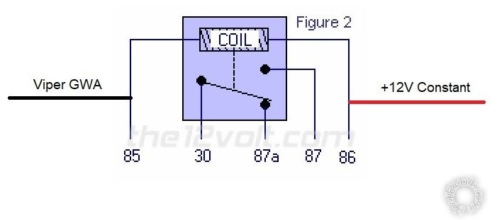
 With the Viper GWA connected to Pin 85 and +12V Constant connected to Pin 86, the relay will draw no power until the Viper is armed. Once the Viper is armed, it outputs the GWA signal which energizes the relay.
Remember that we are not including anything connected in any way to Pins 30, 87 and 87a. When the Viper outputs the GWA signal the relay will energize and draw current. While there is a momentary surge, current draw for a common 30/40 Amp relay is less than ~80 mA.
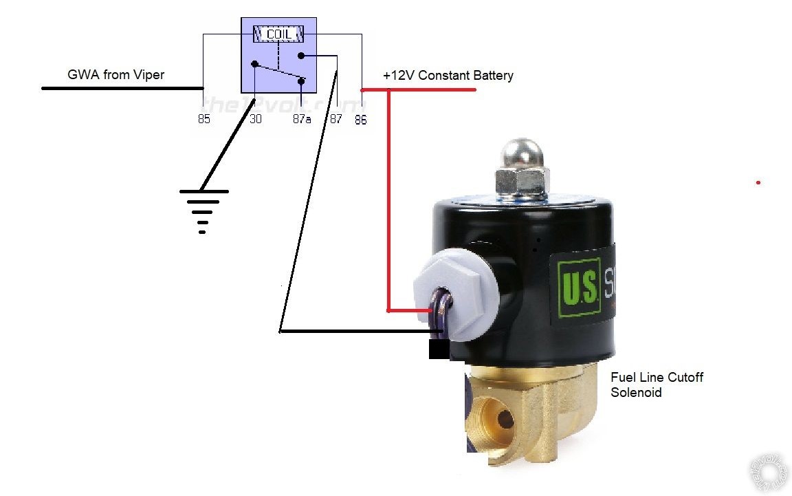
 This circuit will draw no current when GWA is not present. The Viper only outputs the (-) GWA signal when it is armed. The N.O. Fuel Cutoff Solenoid will allow fuel to pass without drawing any power. Wired this way, both the relay and the Fuel Cutoff Solenoid will be drawing power while the Viper is armed and the engine is OFF. This will deplete the vehicles battery pretty quickly. Going with a more common N.C. Fuel Cutoff Solenoid will draw less power during this period but requires the solenoid to be powered to enable fuel supply to the engine. This is not a big deal with a running engine but adds another point of failure during normal operation (power loss to solenoid ).
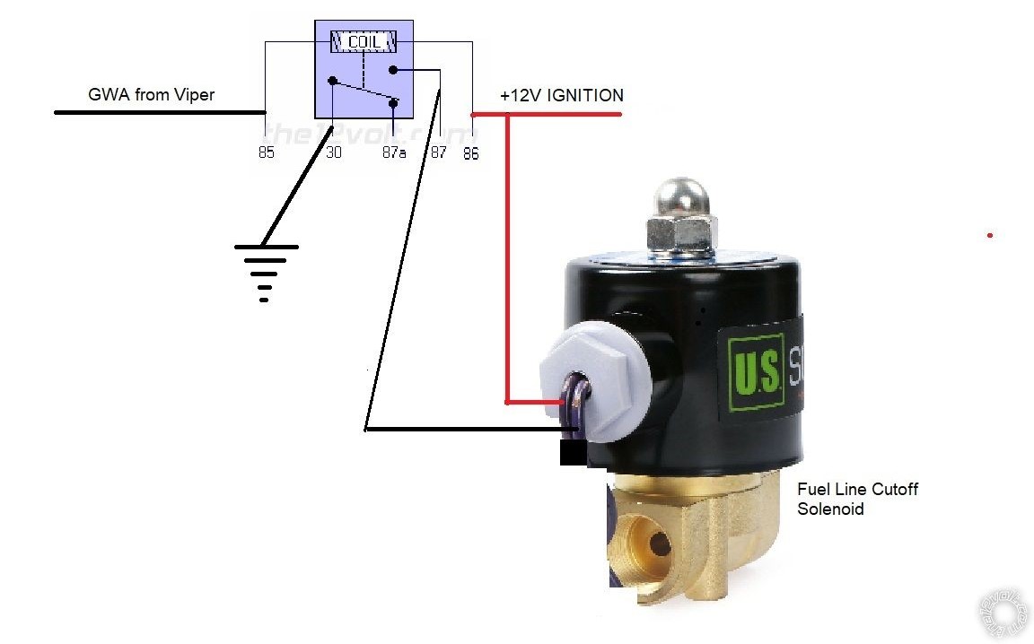
Assuming that the vehicle needs an Ignition type circuit to allow the engine to run, switching the Red +12V Constant input power to a switched Ignition source would prevent the constant battery drain while GWA was present. Wired with IGN, the circuit would only draw current while IGN was ON and GWA was present. Below is the same circuit using IGN as power.

