


latched on/off output


Posted: August 03, 2012 at 3:35 PM / IP Logged
 I am attempting to do the following relay setup. I am wanting to use a 12V+ ignition wire to activate the setup and for it to return to a off position after the ignition looses power. Is there a way to do that with this setup or would I have to add a additional relay to the ignition wire? Thanks

Posted: August 03, 2012 at 7:39 PM / IP Logged
Posted: August 04, 2012 at 12:58 AM / IP Logged
Posted: August 05, 2012 at 1:07 PM / IP Logged
Posted: August 05, 2012 at 1:08 PM / IP Logged
Posted: August 06, 2012 at 3:15 AM / IP Logged
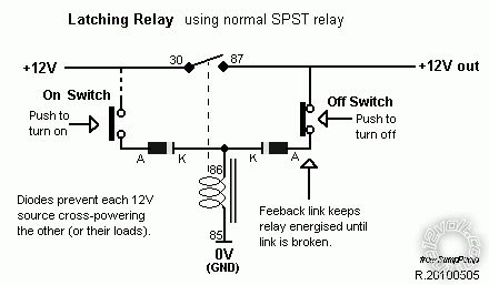 That diagram's +12V should be IGN +12V so that it deactivates with IGN off.
The "+12V out" can be the aircon if that IGN +12V has enough current rating, though I'd probably recommend the 12V out feeds another relay (#86) that connects an appropriate or new fused +12V from the battery (#30) to the aircon (#87).
The second relay not only takes the load of the "latching relay's" IGN +12V, but also allows future signals to kill the aircon - eg, aircons often turn off at low revs or idle. IE - a low RPM signal could break the 2nd relay's GND (#85) or +12V signal (#86).
FYI - that diagram exists in various places, but the12volt's
That diagram's +12V should be IGN +12V so that it deactivates with IGN off.
The "+12V out" can be the aircon if that IGN +12V has enough current rating, though I'd probably recommend the 12V out feeds another relay (#86) that connects an appropriate or new fused +12V from the battery (#30) to the aircon (#87).
The second relay not only takes the load of the "latching relay's" IGN +12V, but also allows future signals to kill the aircon - eg, aircons often turn off at low revs or idle. IE - a low RPM signal could break the 2nd relay's GND (#85) or +12V signal (#86).
FYI - that diagram exists in various places, but the12volt's Posted: August 06, 2012 at 4:15 AM / IP Logged
Posted: August 06, 2012 at 4:33 AM / IP Logged
Posted: August 06, 2012 at 4:49 AM / IP Logged
Posted: August 06, 2012 at 5:32 AM / IP Logged
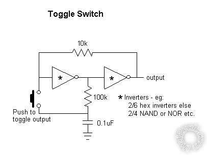 ... where the circuit is powered by IGN +12V.
And the output controls the relay.
I suspect it powers up in the on state (+12V out), hence connect that to a relay connected to IGN +12V...
Or any flip-flip or divide-by-2 circuit (eg, the CD4017 can be div-2 to div-10 etc).
Or an on-off switch - push-button or rotary...
... where the circuit is powered by IGN +12V.
And the output controls the relay.
I suspect it powers up in the on state (+12V out), hence connect that to a relay connected to IGN +12V...
Or any flip-flip or divide-by-2 circuit (eg, the CD4017 can be div-2 to div-10 etc).
Or an on-off switch - push-button or rotary...
 Printable version
| You cannot post new topics in this forum You cannot reply to topics in this forum You cannot delete your posts in this forum You cannot edit your posts in this forum You cannot create polls in this forum You cannot vote in polls in this forum |

| Search the12volt.com |
Follow the12volt.com 
Monday, March 23, 2026 • Copyright © 1999-2026 the12volt.com, All Rights Reserved • Privacy Policy & Use of Cookies

Monday, March 23, 2026 • Copyright © 1999-2026 the12volt.com, All Rights Reserved • Privacy Policy & Use of Cookies
Disclaimer:
*All information on this site ( the12volt.com ) is provided "as is" without any warranty of any kind, either expressed or implied, including but not limited to fitness for a particular use. Any user assumes the entire risk as to the accuracy and use of this information. Please
verify all wire colors and diagrams before applying any information.
