


2010-2012 Kia Forte Remote Start Pictorial
Home /
the12volt's Install Bay /
Car Security and Convenience - Alarm/Remote Start Pictorials / 2010-2012 Kia Forte Remote Start Pictorial ( Topic Closed)


Posted: January 07, 2012 at 10:13 AM / IP Logged
 2 phillps head Screws on bottom corners
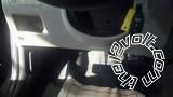
 This is a shot of the side cover
 A shot of the side cover clips
 2 Phillps head screws for the front panel
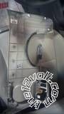 Behind front dash panel showing clips
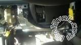 5 10mm bolts hold this on
 2 phillps head screws on each side and one underneith
 Brake - White at switch
 Horn - Red at multi function switch
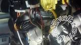
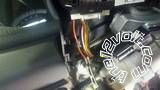
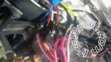 12v- White and Black Both 30Amps
Ing - Blue,Acc1 Orange,Acc2 Yellow, Starter White
12v- White and Black Both 30Amps
Ing - Blue,Acc1 Orange,Acc2 Yellow, Starter White
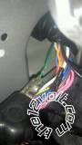 Lock - Green Harness coming from door test using switch on door
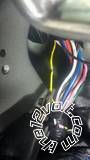 Unlock - Yellow Harness Coming From door test using switch on door
 Park Lights - Orange at switch Negitive trigger
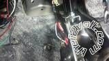
 Tach - Yellow at cylinder 4 coil
 Trunk/hatch release - Blue/Black Negitive trigger If hatch test using Switch on back door. If trunk test using release button on factory remote


Posted: January 12, 2012 at 10:15 PM / IP Logged
Posted: January 13, 2012 at 4:55 AM / IP Logged
Sorry, you can NOT post a reply.
This topic is closed.
 Printable version
| You cannot post new topics in this forum You cannot reply to topics in this forum You cannot delete your posts in this forum You cannot edit your posts in this forum You cannot create polls in this forum You cannot vote in polls in this forum |

| Search the12volt.com |
Follow the12volt.com 
Thursday, April 16, 2026 • Copyright © 1999-2026 the12volt.com, All Rights Reserved • Privacy Policy & Use of Cookies

Thursday, April 16, 2026 • Copyright © 1999-2026 the12volt.com, All Rights Reserved • Privacy Policy & Use of Cookies
Disclaimer:
*All information on this site ( the12volt.com ) is provided "as is" without any warranty of any kind, either expressed or implied, including but not limited to fitness for a particular use. Any user assumes the entire risk as to the accuracy and use of this information. Please
verify all wire colors and diagrams before applying any information.
