I should first ask what the total current of the LEDs is, and after getting an answer, describe and ask which method you prefer (resistor or dimmer), and thereafter describe the gritty detail following....
But you being a Newbie, I may as well hammer you!

Actually it's me... It'll be sun-up in a few hours, and I started this (below) without much pre-thought and it got out of hand. (Again!) [Sorry, you are probably too new to know my, er,
behavior.]
But I'll keep the full onslaught in case you can follow it and in case it provides some ideas...
Arguable the simplest solution is an SPDT relay (5 pin) with pin 30 to the LEDs, IGN +12V to 87a, and 87 from battery +12V via a resistor of R-Ohms & probably high Wattage rating (see below).
With #85 to GND, the beam's or taillight's (whichever you prefer) switched +12V energises the relay's #86 thus the relay's #30 contact changes over from #87a to #87.
The resistor R is added in series to the LEDs when the relay is on (ie, +12V via R to 87 and out thru 30 to the LEDs).
It's value can be found by experimentation to give the dimness you require...
.. or one can estimate its value and power rating if the number of series LEDs is known (probably 3 - white LEDs are about 3.3V each, hence ~10V if 3 in series) as well as the total LED current, else the number of parallel strings and current per string or LED - probably 20mA each LED/string. (A 10A ammeter or DMM is probably easiest, and best.)
Alternatively, to f.ex halve the current and hence about half the brightness, find what value resistors are used, how many are used, and the get a resistor of value R Ohms where R = r/n and r = each (string's) resistor value (Ohms), and n is the number of strings or resistors.
The resistor's power/Wattage rating is based on IxIxR where I is the total LED current at full/normal brightness. For half current (R = r/n Ohms), the rating should exceed 1/4 of IIR (ie, it's I/2 x I/2 x R).
Confused? A diagram may explain the circuit better, but the total LED current needs to be known for an estimate of the resistor.
There are numerous ways of making that Resistance estimate, and if unknown it can be assumed there are 3 LEDs in series (plus a resistor) in each string, though some may use 4 (white) LEDs and maybe no resistor.
ALTERNATIVELY - and more elegant and arguably simpler - use a
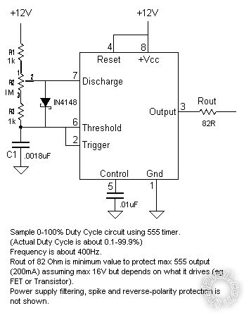
PWM dimmer as found in most modern vehicles for dash etc dimming and switch that in. (Or build your own if so inclined... a simple 555 circuit driving a MOSFET.)
[ FYI - Dash dimmers are usually designed for up to 10A which is lots of 20mA LED strings.
EG, up to 10A/20mA = 500 20mA strings, each probably with 3 LEDs, hence 500 x 3 = 1500 dimable LEDs! ]
With a PWM dimmer you set the appropriate dimness, and maybe tape over its
dial to prevent drift.
Note that PWM dimmers don't get hot like resistors do - very little power is wasted.
The only catch is that most PWM dimmers are grounding - ie, +12V goes to the LEDs/lights which then ground via the dimmer.
But that's no major problem; the -ve end of the LEDs goes to the relay's 30' 87a to GND; and 87 via the dimmer to GND.
The relay is still activated by the light circuit (ie, switched +12V to 86) but the +12V supply to the LED +ve end is either through diodes, else another (SPDT) relay - especially if the LED current is high (above say 3A or 5A, though 10A diodes are available).
But I'll save that - and the diagram(s) - until you respond to the above with whatever you can; whether it's confusion or the Amperage and maybe resistor & string/LED info etc.
BTW - PWM dash dimmers down here are usually ~$10 from auto wreckers/recyclers, though I hear that some have apparently walked out from "self-serve" wreckers.


 Topic Closed)


 Whilst you decide if you want the (clever, superb, power efficient, nice tech bling) dimmer solution, I'll consider the wiring & diagram for it.
 Printable version


