the12volt.com spacer
icon

confirmation of wiring diagram needed.


Post ReplyPost New Topic
< Prev Topic Next Topic >
eversham 
Member - Posts: 4
Member spacespace
Joined: May 15, 2013
Location: United Kingdom
Posted: May 15, 2013 at 3:58 PM / IP Logged  
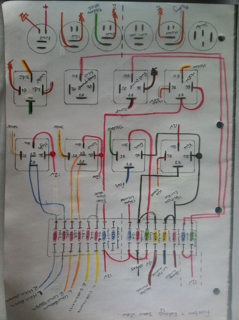
Hello. Could someone take a quick look at this wiring diagram I have made for my track car to check if its all ok. I am basically making my own fuse and relay panel to replace the original and making up new looms.
Many of the looms like for horn, heater fan, indicators etc are copies of the originals which are fine, but it's mainly the headlight circuit I need checking as it used to use a 5 relay dim dip system which I want to simplify to a 2 relay item. I believe from the layout of the original wiring and the colours BROWN / yellow and BROWN / white the system uses a negative switched system. Car is a 1988 Escort RS Turbo.
Any help would be great.
confirmation of wiring diagram needed. - Last Post -- posted image.
oldspark 
Gold - Posts: 4,913
Gold spacespace
Joined: November 03, 2008
Location: Australia
Posted: May 16, 2013 at 1:07 AM / IP Logged  
A few things...
No fuse (flink aka fuselink) shown between the 12V source and the fusebox. That depends on the source proximity, its risk of short etc, and may depend on what the source is for a particular load - eg, the alternator is the +12V source for my headlamps (somewhat pedantic and oldskool, and irrelevant for LEDs & HIDs).
As a general rule for competition (except damage-expecting demolitions etc), only the supply side to headlight relays is fused - not each individual filament. But if each filament is fused as per your diagram, each relay feed should still be protected by something (typically rated larger than the sum of the outputs, ie 25A or 30A or 40A etc in your case).
I suggest self-resetting circuit breakers be used for headlights - maybe a 30A CB supplying the relay which then splits into 2 10A fused feeds, else a 20A or 30A CB feed and no downstream fuses.
What is best or chosen depends on weight versus light output - and maybe wiring complexity - for a given application.
Such CBs are also desirable for other "critical" circuits (maybe wipers?).     
Your upper-left relay IMO makes no sense. The 30 +12V thru 87 to the stalk & heater fuses is fine, but its 86 (also to the 86 of the next relay) should be from some switch etc, but it looks as if it's supposed to be a 12V 10A & 20A source to the brake switch and wiper.     
Otherwise it looks ok assuming the ECU relay is reverse polarity protected (series diode line-end to 86, else between 85 to GND) and whatever sensing is used to cut the fuel pump relay (eg, alternator charge light or spark sensor or air-flap etc).
eversham 
Member - Posts: 4
Member spacespace
Joined: May 15, 2013
Location: United Kingdom
Posted: May 16, 2013 at 3:38 AM / IP Logged  
Cheers for the help. The relays without fused 12v supply's I was going to use fused relays with the fuse built in. The car is still to be road legal which is why I wanted to keep the headlights on separate circuits.
The upper left relay is the Ignition relay and is wired as per the standard car. The relay next to it is the fan relay and it needs an ignition source so I piggy backed it off the relay. The switched live from the ignition barrel joins to this pin 86, the diagram maybe isn't too clear. Should I change this?
The 12v feeds are from a distribution box 6 inches from the fuse panel which, in turn, is a splitter fed from the battery/starter/FIA kill switch etc.
The ECU and fuel pump relays don't need looking at as they are already wired in from the engine management loom.
oldspark 
Gold - Posts: 4,913
Gold spacespace
Joined: November 03, 2008
Location: Australia
Posted: May 16, 2013 at 4:48 AM / IP Logged  
The fused relays do not protect the wiring from the 12V source to the relay.
And those fuse-integral relays are intended to avoid the need for the downstream fuses that you have.
Not that I'm up with recent automotive wiring regulations whether locally or anywhere else, but IMO your diagram does not represent separate circuits - the L&R share the same relay and same upstream protection. The only advantage is that a fault on one side will blow its fuse and the other side remains intact - ASSUMING the upstream fuse (and relay) is appropriately designed/rated (a 30A fuse can blow faster than a 10A fuse...).
But if that meets your local regs, then fine. But I'd use standard unfused relays - why have 3 10-30A fuses in series when only 2 is required?
[ FYI - Being somewhat obsessive, I used individual relays with copious wiring gauge (30A+) and 10A else 15A self resetting breakers for each of the 2 low filaments & 4 highbeam filaments. I recall mounting the relays from front to rear in order of inner/dedicated highbeam, outer highbeam, and lowbeam and opposite-side foremost with same-side beams to the rear. The front highbeam feeds had a 100A flink and the lows had a 60A flink. IE, those flinks would only ever blow if the relay feed wires shorted. I was intending the separate CBs to be straight off the battery, but it was a quick & interim install using on-hand rugged dual-relay packs instead of my final intended micro-ATS CB & micro-relay implementation. ]
Keep in mind that SPST (on-off; 4-pin) relays that are to be on only with IGN should still (IMO) be fused and supplied from the battery - only their #86 +12V need be from IGN (often the IgSwitch for reliability, though ECU related stuff can be from the ECU relay output (with due regard for coil spikes, but ECUs should be spike protected!).
That's probably what you intend but to cover possible misunderstanding...
Elsewhere I have mentioned the difference between a kill switch and a battery isolation switch (and moronic Regulators that combine the two in a single switch, or otherwise allow "remote" isolation switches to be on the hot side (+12V)... d'oh!).
I forgot that the FPR will be controlled by the ECU. (I'm too used to my vintage and other carbied vehicles, and recalcitrant Euro EMSs that do not control the fuel pump.)
And tho any "IGN" (or audio etc) relay should be polarity protected, certainly every EMS/ECU relay will be polarity protected.. surely?
eversham 
Member - Posts: 4
Member spacespace
Joined: May 15, 2013
Location: United Kingdom
Posted: May 16, 2013 at 11:53 AM / IP Logged  
So, to clarify a few points, seperately fuse the 12v feeds to the fusebox with CB's or inline flinks.
I wanted to keep relays to a minimum as I'm short on space on the panel, hence the two relay, rather than four, system was used.
With the ignition relay is that setup with the fan relay piggybacked off the IGN pin 86 ok as this us where the switched feed from the IGN switch goes. Or, shall I take the fan pin 86 feed from the IGN switch itself.
The kill switch/isolator is a combined unit which dumps the alternator charge through a resister to ground to kill everything and is connected to break battery +.
The toggle switches to turn on the fuel pump relay, IGN relay etc are connected to break or connect the ground. Is this the best way?
The car doesn't have to comply with any race regs as such, I just want it to be safe.
Thanks for your input so far. It's been a great help.
oldspark 
Gold - Posts: 4,913
Gold spacespace
Joined: November 03, 2008
Location: Australia
Posted: May 16, 2013 at 3:26 PM / IP Logged  
To simplify protection (fusing etc), each supply wire from a power source needs protection by a fuse (or CB etc).
The fuse shall be as close to the power source as possible/practical.
The fuse must be rated no higher than the lowest rated downstream cable and component until the next fuse. (eg, battery - 60A flink with 60A or higher cable to >=60A fusebox, then smaller fuses protect their wires and loads.)   
My relay per filament was merely an example of an "electrically robust" system that survived front impacts. (And also makes headlight aiming much easier LOL.)
Since space is a premium, ditch the filament fuses and use a single fuse into the relay - but make sure cables from the relay are rated NO LESS than the (lowest rated) upstream fuse.    
IMO the fan relay 86 source doesn't matter unless the IGN relay can fail and the engine keeps running.
The alternator dumps into a resistor - are you sure? That's either a heck of a big resistor, else a very small alternator!
That would only be done for a stator system & not a typical automotive alternator (or generator). Even then, a stator system is more likely to be opened rather than shorted to GND.
I think you'll find any such resistor would be a short, but for normal alternators, merely the rotor power (voltage regulator) supply would be cut or shorted to GND. But again, a kill switch should kill the engine; then the isolate switch should isolate ALL vehicle electrics from the battery.
Re your single combined kill & isolate switch. For typical vehicles I consider that unsafe.
Since that switch must be in the +12V line between the battery & alternator and the rest of the vehicle, assuming it's not near the battery terminal it's a lot of hot wiring that could short in and accident or fire.
Hence for accident & fire safety reasons, remote isolation switches should (or must!) be in battery's GND circuit. But that requires a separate circuit for the engine kill, though it does isolate the alternator from the battery, and even protects against panel/body short direct to the +ve battery terminal.
As on motorbikes, the engine kill switch merely kills the engine and leaves everything else connected (lights etc).
I know of the odd competition that specifies a single engine kill and battery isolate switch. I expect they won't change that IMO stupid and irresponsible stipulation until someone dies...
GND or +12V switching of relays...?
In principle either can be used.
In practice, hot or +12V switching is preferred so that a short won't turn or keep relays on - eg, water/moisture to GND, frayed wires, etc. GND switching is otherwise preferred so save one wire or more, and to enable simple joining of alternate inputs/switches.
And of course, the FPR is controlled by the ECU (else alternator or spark etc) and not merely a toggle switch...
Safety - yeah, I only just clicked that it was an old Escort. I'd be ditching its electrics too!
And hopefully they don't have the old (TC model?) Cortina fault where the fuel line pops out of the carby and sprays the engine bay. The resulting heat was nice on cold days, but other vehicles fit heaters rather than flame engine bays. But I liked the design as an example of why you do NOT use fuel pump control to kill engines - at least for carbied cars - and hence never oil-pressure controlled fuel pumps. (If the pistons also holed because of the leaning mixture, the relevance to EFI engines is almost complete.)
eversham 
Member - Posts: 4
Member spacespace
Joined: May 15, 2013
Location: United Kingdom
Posted: May 16, 2013 at 4:28 PM / IP Logged  
Excellent. Thanks very much for your help. Ill see how I get on!

Sorry, you can NOT post a reply.
This topic is closed.

  Printable version Printable version Post ReplyPost New Topic
You cannot post new topics in this forum
You cannot reply to topics in this forum
You cannot delete your posts in this forum
You cannot edit your posts in this forum
You cannot create polls in this forum
You cannot vote in polls in this forum

  •  
Search the12volt.com
Follow the12volt.com Follow the12volt.com on Facebook
Wednesday, May 14, 2025 • Copyright © 1999-2025 the12volt.com, All Rights Reserved Privacy Policy & Use of Cookies
Disclaimer: *All information on this site ( the12volt.com ) is provided "as is" without any warranty of any kind, either expressed or implied, including but not limited to fitness for a particular use. Any user assumes the entire risk as to the accuracy and use of this information. Please verify all wire colors and diagrams before applying any information.

Secured by Sectigo
the12volt.com spacer
Support the12volt.com
Top
the12volt.com spacer