This is a quick Pictorial on the Ford Freestar. Apparently not a real popular vehicle, as Ford only made it from 2004 through
2007. This one was a 2007 with Remote Keyless Entry, AutoHeadlights and the Factory Alarm. Fairly easy vehicle to do with
the appropriate system and parts.
Here are the parts used for this install :
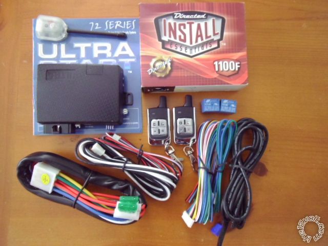
The Ultra Start U1272 has a Flex Ignition output that can support the Freestar's Accessory2 ignition wire and programming
that will allow it to use this vehicles N.C. type Factory Hood Pin. There are other, good quality, remote start systems available
that have similar features.
The Directed 1100F bypass module has been discontinued but is a quality module that will handle the Freestar's PATS3 system.
However, two factory keys ( non-clone ) are required for bypass module programming. The 1100F can be found at various on-line
retailers for under $20.
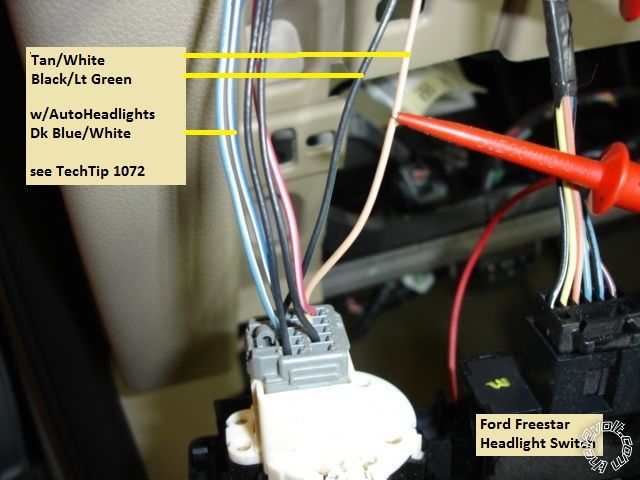
The two 10 Amp mini-relays were used to interface this vehicles unique Parking Light system requirements. For more info,
here is a link to a ZIP file with the Directed TechTip #1072 :
https://www.the12volt.com/installbay/file.asp?ID=1076 Vehicles
without AutoHeadlights will only need one relay.
Here is the wiring connections :
U1272
6 Pin Ignition Harness
1 Yellow (+) Starter Output Dark /Green @ main ignition harness
2 Green (+) Accessory Output Violet/Orange @ main ignition harness
3 Red (+) +12V constant Red @ main ignition harness
4 Red (+) +12V constant Lt GREEN/ Purple @ main ignition harness
5 White (+) Flex Relay Output BLACK/ Lt Green @ main ignition harness *** Program U1272 for ACC2
6 Blue (+) Ignition Output WHITE/ Yellow @ main ignition harness
2 Pin Harness
Black (-) Main Chassis Ground Chassis Ground
White Selectable Parking Light Output Pin 86 of both mini-relays ( set U1272 for (+) output. See TechTip 1072 )
9 Pin Harness
1 Yellow (-) Rearm Output Not used
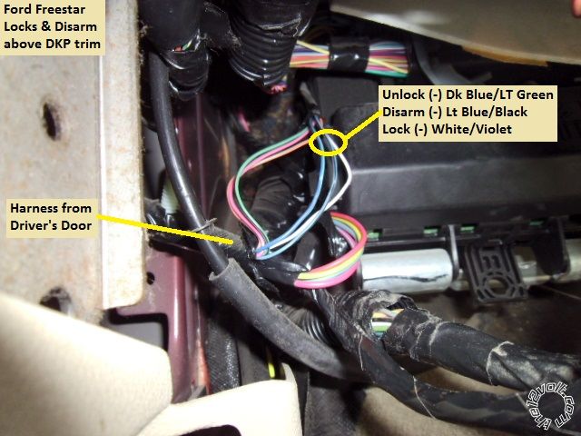
2 Brown (-) Disarm Output Light Blue/Black @ DKP in harness from drivers door
3 Black (-) AUX1 Output Not used
4 RED / White (-) Trunk Release Not used ( Trunk unlocks with doors )
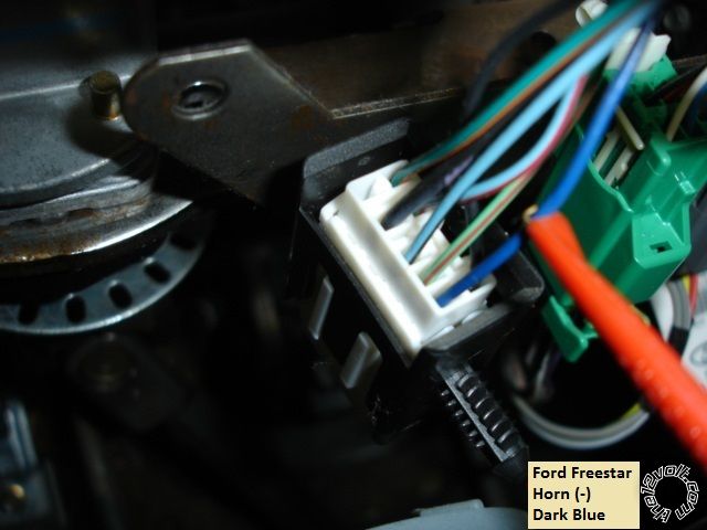
5 WHITE/ Blue (-) Horn Output Dark Blue @ White 10 Pin connector, right of steering column
6 Pink (+) Brake Input RED / Lt Green @ Brake Pedal Switch
7 GREEN / WHITE (-) Hood Pin Input Violet @ Factory Hood Pin ( Program U1272 for Hood Pin = N.C. )
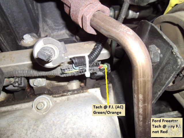
8 Blue/White (AC) Tach Input GREEN/ Orange @ #6 F.I. ( any F.I.; not the Red wire )
9 Blue (+/-) Glow Plug/WTS/Trigger Input Not used
Lock Harness
Green (-) Lock WHITE/ Violet @ DKP in harness from drivers door
Blue (-) Unlock Dk Blue/Lt Green @ DKP in harness from drivers door.
3 Pin Bypass Harness
Red +12V 1100F Red wire, 4 Pin harness
Black Ground 1100F Black wire, 4 Pin harness
WHITE/ Violet (-) GWR 1100F Blue/White, 4 Pin harness
1100F
4 Pin Plug
Red +12V to U1272 Red on 3 Pin bypass harness
Black Ground to U1272 Black on 3 Pin bypass harness
Blue/White GWR to U1272 WHITE/ Violet on 3 Pin bypass harness
9 Pin Plug
Pink Ignition to U1272 Ignition Output, thick Blue on 6 Pin plug
GREEN/ Red RX to Freestar Gray/Orange at Pin 3 of 4 Pin transponder plug
GREEN/ Red TX to Freestar WHITE/ Lt Green at Pin 4 of 4 Pin transponder plug
Bulldog Security has many good pictures along with their wiring guide info. This info also includes a diagram for Parking
Light control, similar to Directed's TechTip #1072, but with Bulldog specific wire names / colors. Here is a link :
http://diagrams.marktoonen.nl/printlist.aspx?MakeID=18&ModelID=17322
Disassembly :
Remove the three 8mm screws at the bottom edge of the drivers lower dash panel. Then pull the lower dash panel straight away
from the dash. There are 5 plastic retainer clips along the top edge. This will expose the metal knee panel. Remove the two 8mm
screws at the top corners and remove the metal panel. All the necessary wiring is now accessible. No need to remove the steering
column covers.
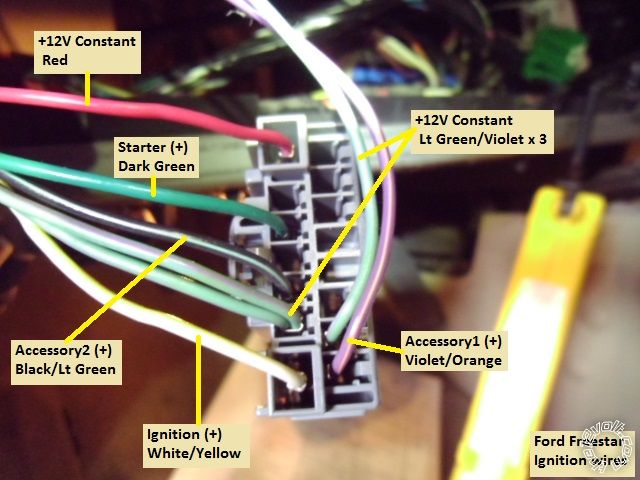
Wiring :
This is a photo of the main ignition harness, disconnected from the ignition switch, with the wires indicated. These are thin
gauge wires and rated at 20 Amps.
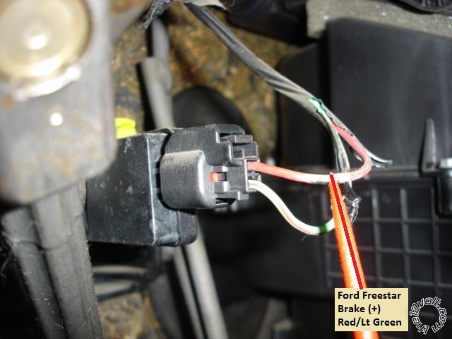
This is a picture of the Brake wire, at the brake pedal switch.
Here is a picture of the Horn wire. Use caution when testing for this wire as it is in a Yellow Air Bag harness. Do not unplug this
connector with the battery connected.
.jpg)
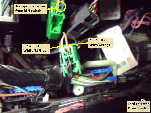
Next is the Transponder connector ( just to the right of the horn connector ). The transponder wire colors listed in various
bypass module install guides give the wire colors on the car side of this connector. The wire colors on the side going to the
ignition switch are different. This connector is shown unplugged for photo and wiring.
Here is a photo of the door lock and disarm wires. This is the door harness found just above the DKP trim, next to the SJB.
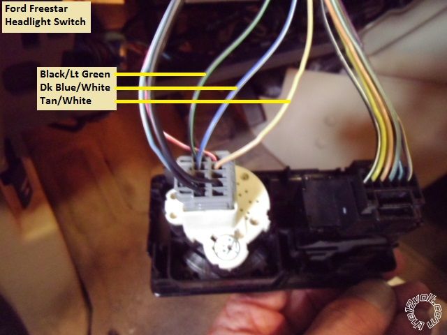
These are pictures of the Headlight switch harness.
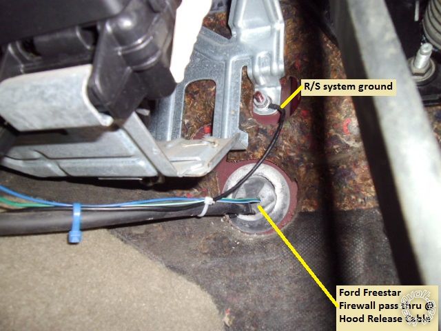
This is a photo of a convenient firewall pass-thru grommet. It contains the hood release cable. Also shown is a chassis ground
location.
Here is a picture of a good Tach source, the #6 Fuel Injector.
There is plenty of room under the dash for R/S and bypass module placement. This vehicle has automatic RAP shutdown
after ten minutes. All wires should be verified with a Digital Multi Meter prior to making your quality solder connection.
Soldering is fun!


 Topic Closed)


 Printable version


