


2014 Honda Odyssey Remote Starter Pictorial
Home /
the12volt's Install Bay /
Car Security and Convenience - Alarm/Remote Start Pictorials / 2014 Honda Odyssey Remote Starter Pictorial ( Topic Closed)


Posted: November 08, 2015 at 7:31 PM / IP Logged
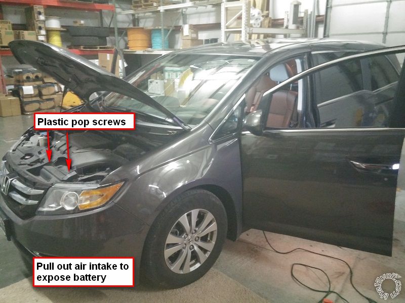
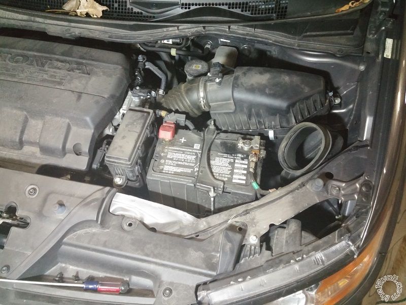
 The battery is hidden, but a simple removal of the air intake exposes it. Just 2 plastic pop screws to take it out
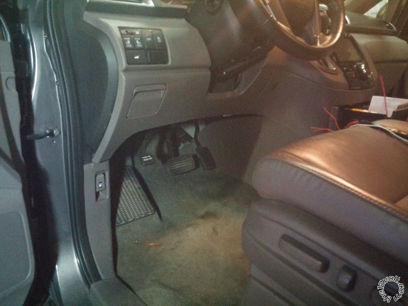
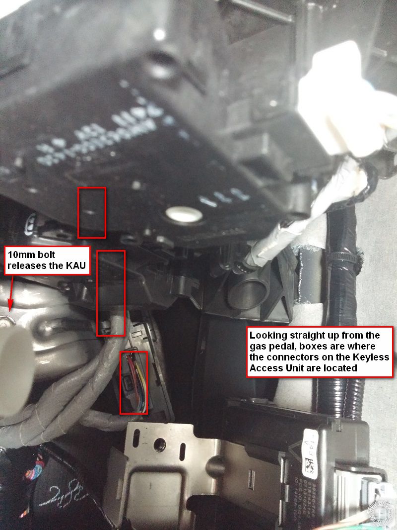
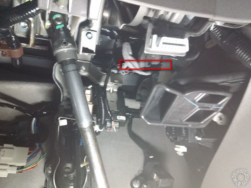
 Initial locations. I did not need to remove any body panels except the A-pillar for the antenna, because the location of the Keyless Access Unit [KAU] won't be any more accessible with the lower dash removed (at least I didn't see a better way to get to the wires). I apologize if the pictures are difficult to look at and figure out the angle, I had a hard enough time myself getting into the right angle to do the work.
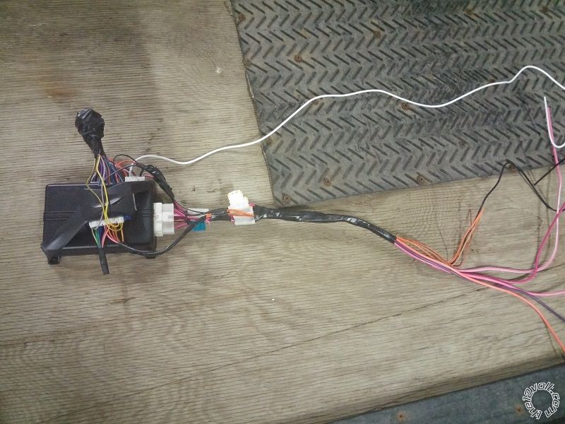
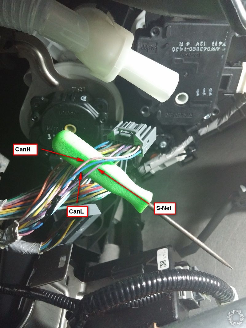
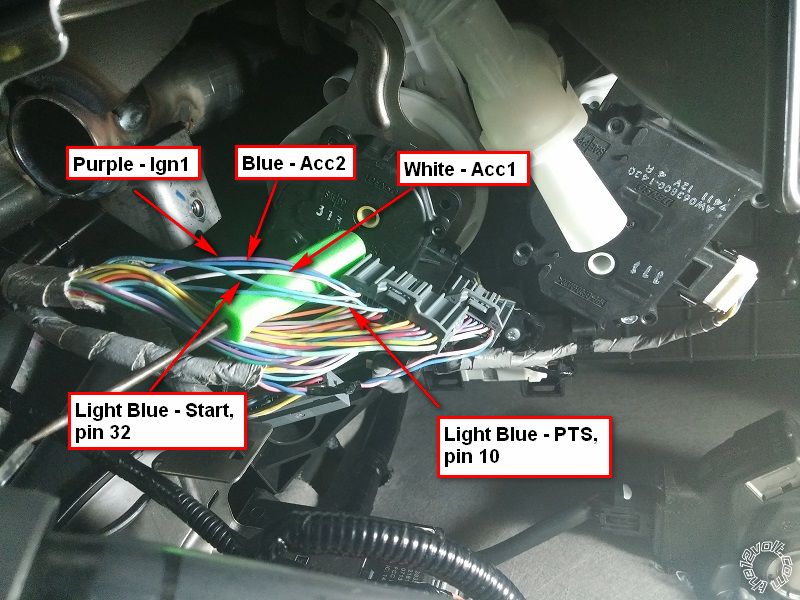
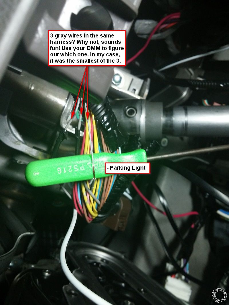
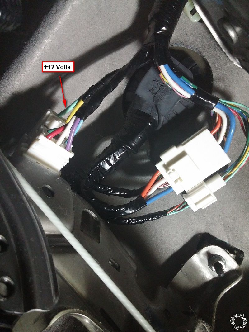
 After taking down the KAU and unplugging it, here are the wires to be concerned with. As you will see, there are 2 light gray wires in the same plug so be careful not to hook those up backwards. The install guide from iDatalink is very specific about the location of the wires which made it fairly easy to figure out. Also, there is another picture with the parking light wire that highlights how convenient it is to have the same color wire multiple times in the same harness. Make sure to test with a DMM (as if you don't already test everything with a DMM, right?)
 Just as a note because I wasn't expecting it, I have seen a few A-pillars that have a safety clip that won't allow you to entirely remove the A-piller plastic, but in the 2014 Odyssey there is an 8mm bolt under the SRS plastic emblem
 That is essentially all that I needed to get my remote starter to be a success, along with programming the ADS-ALCA and Viper. However, I will have to add in that I had a very difficult time actually connecting and soldering the wires in. The KAU is pretty high up, and being a bigger guy (6'3") it got rough at times.
There are also some caveats to having a remote starter in this van. As with any other PTS vehicle, once you open a door, the vehicle will shut off. Also, while remote started, the factory remote is mostly useless. You cannot unlock, lock, open sliding doors, or open the liftgate. Furthermore, the 'touch to unlock' feature will not work either. The Viper remote can lock and unlock during remote start. So, if you have a wife like me who likes keeping her keys buried in her bottomless purse, this may become an point of difficulty. Just saying.
Hope you like my first time install post, and hope it helps out.
Rauenpc
That is essentially all that I needed to get my remote starter to be a success, along with programming the ADS-ALCA and Viper. However, I will have to add in that I had a very difficult time actually connecting and soldering the wires in. The KAU is pretty high up, and being a bigger guy (6'3") it got rough at times.
There are also some caveats to having a remote starter in this van. As with any other PTS vehicle, once you open a door, the vehicle will shut off. Also, while remote started, the factory remote is mostly useless. You cannot unlock, lock, open sliding doors, or open the liftgate. Furthermore, the 'touch to unlock' feature will not work either. The Viper remote can lock and unlock during remote start. So, if you have a wife like me who likes keeping her keys buried in her bottomless purse, this may become an point of difficulty. Just saying.
Hope you like my first time install post, and hope it helps out.
Rauenpc


Posted: November 09, 2015 at 7:21 PM / IP Logged
 Those iDatalink modules make things pretty easy.
Posted: November 11, 2015 at 9:57 AM / IP Logged
Posted: November 11, 2015 at 7:35 PM / IP Logged
Posted: November 11, 2015 at 9:03 PM / IP Logged
Posted: November 11, 2015 at 9:13 PM / IP Logged
 Hard to make mistakes and easy to verify any setting.
Posted: December 26, 2015 at 8:09 AM / IP Logged

Posted: January 26, 2017 at 10:05 PM / IP Logged
Posted: January 27, 2017 at 5:51 AM / IP Logged
Sorry, you can NOT post a reply.
This topic is closed.
 Printable version
| You cannot post new topics in this forum You cannot reply to topics in this forum You cannot delete your posts in this forum You cannot edit your posts in this forum You cannot create polls in this forum You cannot vote in polls in this forum |

| Search the12volt.com |
Follow the12volt.com 
Saturday, May 23, 2026 • Copyright © 1999-2026 the12volt.com, All Rights Reserved • Privacy Policy & Use of Cookies

Saturday, May 23, 2026 • Copyright © 1999-2026 the12volt.com, All Rights Reserved • Privacy Policy & Use of Cookies
Disclaimer:
*All information on this site ( the12volt.com ) is provided "as is" without any warranty of any kind, either expressed or implied, including but not limited to fitness for a particular use. Any user assumes the entire risk as to the accuracy and use of this information. Please
verify all wire colors and diagrams before applying any information.
