


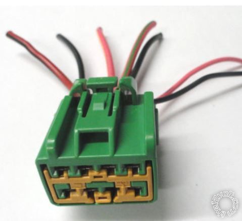
 The above green 5 wire plug connects into power lock/unlock switch of the rest arm bezel on each side (driver & passenger doors). If you have the same green plugs connected to your switches then all in likely you have 5 wire power door locks or others rather call it Type C; take your personal pick.
The way 5 wire works I had already explained earlier in this thread but here I explain it again:
1 wire has (+)12 volts all the time, other wires are normally grounded without working the switch. One or two wires are grounded at all times. One wire is grounded normally but switches to (+)12 volts when the switch is moved to the lock position. One wire is grounded normally but switches to (+)12 volts when the switch is moved to the unlock position.
I never fooled with remote start, does nothing for me so didn't want it and coincidentally the Viper Model 211HV isn't equipped with that feature.
The above green 5 wire plug connects into power lock/unlock switch of the rest arm bezel on each side (driver & passenger doors). If you have the same green plugs connected to your switches then all in likely you have 5 wire power door locks or others rather call it Type C; take your personal pick.
The way 5 wire works I had already explained earlier in this thread but here I explain it again:
1 wire has (+)12 volts all the time, other wires are normally grounded without working the switch. One or two wires are grounded at all times. One wire is grounded normally but switches to (+)12 volts when the switch is moved to the lock position. One wire is grounded normally but switches to (+)12 volts when the switch is moved to the unlock position.
I never fooled with remote start, does nothing for me so didn't want it and coincidentally the Viper Model 211HV isn't equipped with that feature.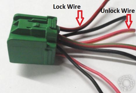 I later found and marked the exampled image above to better visually represent the green plug that is connected to passenger side power lock switch in my 2004 Ford F-250. This better illustrates the 2 correct adjoined Lock/Unlock switch and Actuator Motor wires you'll need to cut before connecting your keyless remote module harness however don't cut them near the switch but rather trace these marked wires and cut them down farther and beneath the passenger side kick panel or logically near where your keyless remote module will be mounted.
Lock Wire = Pink/Black Stripe Wire
UnLock Wire = Pink/Light Red Stripe Wire
I later found and marked the exampled image above to better visually represent the green plug that is connected to passenger side power lock switch in my 2004 Ford F-250. This better illustrates the 2 correct adjoined Lock/Unlock switch and Actuator Motor wires you'll need to cut before connecting your keyless remote module harness however don't cut them near the switch but rather trace these marked wires and cut them down farther and beneath the passenger side kick panel or logically near where your keyless remote module will be mounted.
Lock Wire = Pink/Black Stripe Wire
UnLock Wire = Pink/Light Red Stripe WireIf you wish to post a reply to this topic, you must first login.
If you are not already registered, you must first register.
 Printable version


| You cannot post new topics in this forum You cannot reply to topics in this forum You cannot delete your posts in this forum You cannot edit your posts in this forum You cannot create polls in this forum You cannot vote in polls in this forum |

| Search the12volt.com |
Follow the12volt.com 
Wednesday, April 8, 2026 • Copyright © 1999-2026 the12volt.com, All Rights Reserved • Privacy Policy & Use of Cookies

Wednesday, April 8, 2026 • Copyright © 1999-2026 the12volt.com, All Rights Reserved • Privacy Policy & Use of Cookies
Disclaimer:
*All information on this site ( the12volt.com ) is provided "as is" without any warranty of any kind, either expressed or implied, including but not limited to fitness for a particular use. Any user assumes the entire risk as to the accuracy and use of this information. Please
verify all wire colors and diagrams before applying any information.
