I saw an earlier post showing how to construct a SPDT relay using a flip-flop circuit. I have a different application that I have a few questions on. I created a circuit to reassign the factory mirror turn signal to function as a parking light, yet still retain the functionality as a turn signal (one element bulb). I COULD wire one side of the bulb to the parking circuit and the other side of the bulb to the turn signal. However, when the parking light circuit is in use and a turn signal is initiated, the signal flashes out of sync.
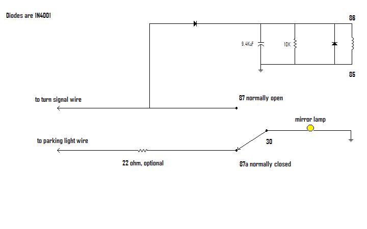
I made this circuit to correct that problem so that the lamp blinks in unison with the front and rear signals, regardless of whether it is being used as a parking light. The circuit uses a relay to share a one element bulb with the turn and park circuits. I would just like to be able to build this circuit using semiconductors, for the fun of it. Here is the circuit I created and two video clips of it in use:
Hint: To better understand the following links, look at the license plate lamp to determine when parking lights are on, as the vids are taken in the dark.
Video of the turn signal (on mirror) with parking lights off: http://s159.photobucket.com/albums/t138/mtt_album/?action=view¤t=parklightsoff.flv
Video of the turn signal (on mirror) with parking lights on: http://s159.photobucket.com/albums/t138/mtt_album/?action=view¤t=parklightson.flv
Here's the only picture I have of it (minus the relay): http://s159.photobucket.com/albums/t138/mtt_album/?action=view¤t=Photo_12-8.jpg (there's one of these in each of the front doors, sorry about the poor quality of the picture, it's all I have)
Notice the mirror turn signal blinks in unison with the rear signals, regardless of whether it is being used as a parking light. The 22 ohm resistor has been added since the video clips. It merely dims the bulb while it is a parking light, but it also serves to distinguish it from the turn signal, which comes on at full brightness (it almost gives it a two element bulb likeness).
I'm using the resistor/capacitor to keep the relay energized during the 'off flash' state of the turn signal (imagine a 50% duty cycle for the turn signal flashing). It is large enough to give the relay coil enough juice to stay energized through the off state flash, maintaining the connection from 87 to 30, but small enough to last only roughly longer than the 50% duty cycle so that the light can go back to being a parking light (87a to 30) as soon as possible after the turn signal is cancelled. Another nice feature of this design is that it does not require me to run a constant power wire in from under the dash, therefore I can house the circuit in each door, rather than under the dash (the relay is merely connecting one of two circuits to the mirror lamp, as needed, and does not provide power to the lamp. That comes from the parking and turn circuits).
Also, on the capacitor being used to keep the relay energized, I would like to come up with some other method. I use two 4700uF caps in parallel, and they are quite large, nearly as large as the relay, each! Since there would be no coil in a solid state version, I hoping I wouldn't need as large a capacitance to maintain the N.O. connection during the off state of the turn signal.
Like I said, this circuit works WONDERFULLY, I would just like to be able to recreate this circuit using solid state componentry as an exercise. If you have any ideas, I would sure appreciate it.


 Printable version


