the12volt.com spacer
icon

Relay Buzzing


Post ReplyPost New Topic
< Prev Topic Next Topic >
bellsracer 
Silver - Posts: 703
Silver spacespace
Joined: January 14, 2006
Location: United States
Posted: June 23, 2009 at 3:30 AM / IP Logged  
iaai... Thank you so much for the diagram. much better.
sns, I didn't want to use the doorpins because I can't. They are computer trigger controlled and isolated from each other. In other words, royal pain in the rear to get to work.
Minna, honto ni arigatou gozaimasu!
Never send your ducks to eagle school.
The difference between ordinary and extraordinary is that little extra.
The 3Ls of life: Learn from the Past, Live for the Present, Look to the Future.
dualsport 
Silver - Posts: 983
Silver spacespace
Joined: September 27, 2005
Location: United States
Posted: June 23, 2009 at 7:53 AM / IP Logged  
i am an idiot wrote:

Relay Buzzing - Page 3 -- posted image.

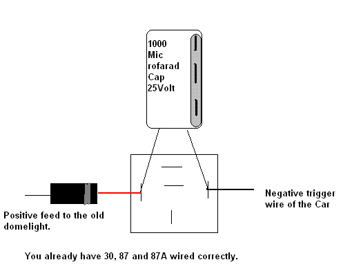
Above diagram is a picture of what "Ween" suggested.     His idea, my picture.

Simply add the capacitor and the diode to your relay.   As ween stated, make sure you polarize the capacitor properly.   The Diode must go on the positive wire.   The banded end of the diode needs to be connected to the relay.  

When the vehicle drops the voltage to fade the lamp, the cap will keep the relay energized for a second or so.   The diode keeps the stored cap voltage from going back into the vehicle.  

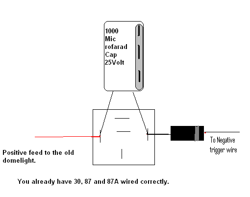
If the control line is the negative side, the diode would need to be on the other side of the coil. It sounds like the 12V side is constant from the description of the setup.
i am an idiot 
Platinum - Posts: 13,693
Platinum spaceThis member consistently provides reliable informationspace
Joined: September 21, 2006
Location: Louisiana, United States
Posted: June 23, 2009 at 8:17 AM / IP Logged  

Thanks for pointing that out Dualsport,  I have made changes accordingly.

Relay Buzzing - Page 3 -- posted image.

Let's Go Brandon Brown. Congratulations on your first Xfinity Series Win. LGBFJB
bellsracer 
Silver - Posts: 703
Silver spacespace
Joined: January 14, 2006
Location: United States
Posted: June 23, 2009 at 9:27 PM / IP Logged  
Awww... Thank you both of you. That's why I love ya guys!
Jya ne
Never send your ducks to eagle school.
The difference between ordinary and extraordinary is that little extra.
The 3Ls of life: Learn from the Past, Live for the Present, Look to the Future.
dualsport 
Silver - Posts: 983
Silver spacespace
Joined: September 27, 2005
Location: United States
Posted: June 24, 2009 at 9:43 PM / IP Logged  
bellsracer wrote:
minna tasukette!
Minna, honto ni arigatou gozaimasu!
Jya ne
Okay, I have to ask.. am I missing a decoder ring or am I just not a cunning linguist? Relay Buzzing - Page 3 -- posted image.
bellsracer 
Silver - Posts: 703
Silver spacespace
Joined: January 14, 2006
Location: United States
Posted: June 26, 2009 at 10:15 PM / IP Logged  

dualsport wrote:
Okay, I have to ask.. am I missing a decoder ring or am I just not a cunning linguist? Relay Buzzing - Page 3 -- posted image.

Please turn your subtitles on your screen to Japanese

"
minna tasukette!
(Everyone, HELP!)
Minna, honto ni arigatou gozaimasu!
(Everyone, I really thank you very much)
Jya ne
(See ya)

We thank you for your compliance. The preceding closed captioning has been brought to you by BellsRacer in association with Teledon Communications. Please PM for more information (seriously) >.<

Never send your ducks to eagle school.
The difference between ordinary and extraordinary is that little extra.
The 3Ls of life: Learn from the Past, Live for the Present, Look to the Future.
petertfm 
Member - Posts: 3
Member spacespace
Joined: January 24, 2010
Location: British Columbia, Canada
Posted: January 25, 2010 at 6:54 PM / IP Logged  
i am an idiot wrote:

Thanks for pointint that out Dualsport,  I have made changes accordingly.

Relay Buzzing - Page 3 -- posted image.

I just wanted to let you know and others that a 1000mic 35 volt capacitor worked great for me!
I used it on a bosch relay, no more buzzing:)
zepdad 
Member - Posts: 4
Member spacespace
Joined: April 27, 2010
Location: Florida, United States
Posted: April 27, 2010 at 10:33 PM / IP Logged  

First time poster.  Thanks for everyone's hard work.  I will use the forum often I can see that now. Relay Buzzing - Page 3 -- posted image.

I have a similar relay buzzing issue.  I think the easiest solution is a reed relay but wanted to check with the experts.  My application is for ambient/courtesy light LED's.  Very low current draw, maybe 150ma for all LED's.  I'm pulling from two diode isolated power sources: 

(1) Headlight circuit for the ambient lighting effect.  No problem with this circuit.  Standard 12v switched power and common ground. 

(2) Map light circuit for the courtesy light (door open) effect.  Two minor problems to overcome with this circuit.  First, the circuit is controlled by a negative trigger wire.  This was easily solved with a relay and the Convert Negative Polarity diagram I found on this site.  Second, the map light circuit is not an immediate 12v on/off circuit.  There is a rapid voltage rise when door is opened and 30-second dimming effect with slow voltage drop when door closed.  The standard auto relay buzzes on door open (briefly) and on dimming (longer). 

The solutions, as I understand them, are either (a) relay with capacitor and diode, but don't think this will solve the door open buzzing, (b) transistor instead of relay, or (c) quiet relay.  Since my application is very low current an inexpensive and quiet reed relay seems to make the most sense. 

Questions:

Is Radio Shack's .5 amp 275-233 Reed Relay sufficient for my needs?  Or would you recommend another brand?

What is the proper wiring?  (Why won't Radio Shack provide spec sheets?) Is a reed relay numbered with standard 30-85-86-87-87a terminals or is it a D pinout used in mini relays?  I found this conversion on another site. 1=86, 2=85, 3=30, 4=87a, 5=87 for the D pinout.  Please confirm or point me in the right direction to wire the reed relay.

Thanks again.


i am an idiot 
Platinum - Posts: 13,693
Platinum spaceThis member consistently provides reliable informationspace
Joined: September 21, 2006
Location: Louisiana, United States
Posted: April 27, 2010 at 10:57 PM / IP Logged  
There should be a diagram or something that comes with it.  85 and 86 are the coil connections on a numbered relay.  There should be a coil drawn between the 2 connections that you will sub 85 and 86.  The other 2 connections are the same as 30 and 87.
KPierson 
Platinum - Posts: 3,527
Platinum spaceThis member consistently provides reliable informationspace
Joined: April 14, 2005
Location: Ohio, United States
Posted: April 28, 2010 at 5:49 AM / IP Logged  
The pins make a cross shape:
____A
__B___C
_
_
____D
B and C are the coil pins and A and D are the contacts. The letters are just for illustration, they are not standard and won't be on the relay.
Kevin Pierson
Page of 4

  Printable version Printable version Post ReplyPost New Topic
You cannot post new topics in this forum
You cannot reply to topics in this forum
You cannot delete your posts in this forum
You cannot edit your posts in this forum
You cannot create polls in this forum
You cannot vote in polls in this forum

  •  
Search the12volt.com
Follow the12volt.com Follow the12volt.com on Facebook
Thursday, October 31, 2024 • Copyright © 1999-2024 the12volt.com, All Rights Reserved Privacy Policy & Use of Cookies
Disclaimer: *All information on this site ( the12volt.com ) is provided "as is" without any warranty of any kind, either expressed or implied, including but not limited to fitness for a particular use. Any user assumes the entire risk as to the accuracy and use of this information. Please verify all wire colors and diagrams before applying any information.

Secured by Sectigo
the12volt.com spacer
Support the12volt.com
Top
the12volt.com spacer