the12volt.com spacer
icon

200ma Won’t Trigger Relay


Post ReplyPost New Topic
< Prev Topic Next Topic >
juvius 
Member - Posts: 31
Member spacespace
Joined: January 10, 2003
Location: United States
Posted: March 18, 2008 at 5:52 PM / IP Logged  
hello,
i looked at all 41 posts in the relay forum and couldn't find an answer, so here's my last resort before i give up.
i just hooked up a dei automate 553 in my 89 saab 900. everything works except i can't figure out why the relay for the supervised dome lights won't work. when i touch the light tester to the BLACK/ white wire (done supervision negative output) i see that there is a negative output. when i connect it to the relay, it will not trigger. i have the relay set up as follows:
30 - negative dome light input switch
85 - BLACK/ white 200mA negative output from alarm
86 - 12V +
87 - Ground
when i click on the alarm with the tester on pin 30 i get nothing, but there is still a very faint reading on 85 (but not near as dominant as the reading when on the BLACK/ white wire when not connected to the relay). by the way, i have tried three different relays. what is wrong here? Do i need to run a stronger 12v and or ground?
thanks
sparkie 
Platinum - Posts: 2,061
Platinum spacespace
Joined: November 06, 2003
Location: Canada
Posted: March 18, 2008 at 6:14 PM / IP Logged  
Use a volt meter set to a DC voltage scale of at least 20 volts. Connect the red probe to terminal # 86 of the relay and the black probe to terminal # 85. Leave the relay wired as you have it and watch the meter reading when you activate the unlock feature of the alarm. If you don't get a reading around 12 volts, then place the red probe onto a know good source of 12 volts. like the main power input to the alarm. If you then get a reading after using the unlock feature of the alarm, you need to check the 12 volt supply to the relay for problems. If you still don't get a reading use a jumper wire to temporarily ground terminal # 85. The relay should activate. If it does, either there is a problem with the alarms output or maybe it needs to be programmed to activate.
sparky
juvius 
Member - Posts: 31
Member spacespace
Joined: January 10, 2003
Location: United States
Posted: March 18, 2008 at 6:38 PM / IP Logged  
now that you mention it, i'm starting to question the 12v source. it's the power wire from the stock alarm that i removed. it's only 16 guage and i'm already running the alarm from it. tomorrow, i'll use a better power supply and better ground on the new alarm and the relay and give the reading a try...
thanks... i appreciate it.
juvius 
Member - Posts: 31
Member spacespace
Joined: January 10, 2003
Location: United States
Posted: March 21, 2008 at 6:27 PM / IP Logged  
well it's not the power supplied to the relay. the relay is hooked up correctly and does trigger when i touch the 85 pin to ground. i went to borrow my dad's meter to test the outputs but he said it's broken. there is definately a negative feed on the BLACK/ white dome light supervision wire from the alarm because it causes my test light to light up when i press the remote unlock button. so now, i'm sure the problem is that the output from the alarm isn't strong enough to trigger the relay. what can i do to make that output stronger?
thanks again
i am an idiot 
Platinum - Posts: 13,667
Platinum spaceThis member consistently provides reliable informationspace
Joined: September 21, 2006
Location: Louisiana, United States
Posted: March 21, 2008 at 7:23 PM / IP Logged  

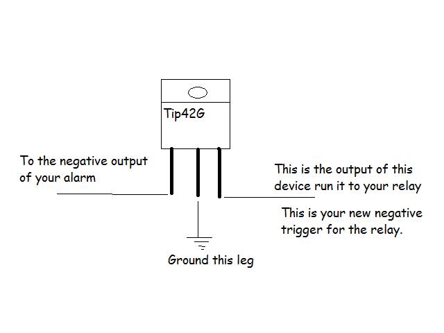
Juvius give me a minute  I will draw you a picture.  The transistor is available at Radio Shack  

http://www.radioshack.com/product/index.jsp?productid=2062613&cp=&sr=1&origkw=pnp&kw=pnp&parentPage=search

i am an idiot 
Platinum - Posts: 13,667
Platinum spaceThis member consistently provides reliable informationspace
Joined: September 21, 2006
Location: Louisiana, United States
Posted: March 21, 2008 at 7:37 PM / IP Logged  
200ma Won’t Trigger Relay -- posted image.
juvius 
Member - Posts: 31
Member spacespace
Joined: January 10, 2003
Location: United States
Posted: March 21, 2008 at 7:39 PM / IP Logged  
thank you very much.... i'll get out to radioshack tomorrow and let you know how it turned out...
thanks again....
i am an idiot 
Platinum - Posts: 13,667
Platinum spaceThis member consistently provides reliable informationspace
Joined: September 21, 2006
Location: Louisiana, United States
Posted: March 21, 2008 at 7:44 PM / IP Logged  

The metal tab of the transistor is connected to the middle leg, which is ground.  If you wanted to eliminate the relay, you could.  If you mount the tab of the transistor to the chassis of the vehicle, it should be good for 4 to 5 amps.  If you do go this route, monitor it for heat.  Leave the lights on via the alarm for a few minutes and see how hot the transistor gets. 

mobile1 
Silver - Posts: 479
Silver spacespace
Joined: February 23, 2004
Location: United States
Posted: March 21, 2008 at 11:54 PM / IP Logged  
Have you checked your main ground for the alarm? There shouldn't be any reason the dome supervision wire doesn't trigger a relay. Thats what its meant for. It does draw its ground current from the main ground of your system.
Where is this unit grounded? Try grounding it in the driver's kick panel. Make sure to scrape away paint first also. If you have a DMM, you can check the resistance of your ground source to the negative post of your battery. Thats where I would start.
juvius 
Member - Posts: 31
Member spacespace
Joined: January 10, 2003
Location: United States
Posted: March 22, 2008 at 1:00 AM / IP Logged  
i just regrounded it and no change... thanks
Page of 2

  Printable version Printable version Post ReplyPost New Topic
You cannot post new topics in this forum
You cannot reply to topics in this forum
You cannot delete your posts in this forum
You cannot edit your posts in this forum
You cannot create polls in this forum
You cannot vote in polls in this forum

  •  
Search the12volt.com
Follow the12volt.com Follow the12volt.com on Facebook
Saturday, April 27, 2024 • Copyright © 1999-2024 the12volt.com, All Rights Reserved Privacy Policy & Use of Cookies
Disclaimer: *All information on this site ( the12volt.com ) is provided "as is" without any warranty of any kind, either expressed or implied, including but not limited to fitness for a particular use. Any user assumes the entire risk as to the accuracy and use of this information. Please verify all wire colors and diagrams before applying any information.

Secured by Sectigo
the12volt.com spacer
Support the12volt.com
Top
the12volt.com spacer