the12volt.com spacer
icon

making a noise sniffer


Post ReplyPost New Topic
< Prev Topic Next Topic >
silentblackhat 
Copper - Posts: 138
Copper spacespace
Joined: January 14, 2005
Location: New Brunswick, Austria
Posted: April 21, 2008 at 5:45 PM / IP Logged  

Hey guys I am trying to figure out how to make the "Walkman Noise Sniffer" so i can solve a noise problem thats being radiated into my CB radio antenna. i get how to do it generally but i need some help. Heres how it basically works:

1.) Get an old AM/FM/Tape walkman

2.) Remove the tape head inside(unsolder it). Some say solder it to the tape head, some say remove it and solder the extension wire to the connections but im not sure what connections. I heard there area few

3.) Extend the tape head connections with an antenna wire (some say shielded antenna wire and some instructions don’t say

4.) Strip 1inch off the end of the extended wire

5.) Press "play" on the walkman tape part and the extended wire will pick up the radiated noise. The louder the noise is in the walkman headphones, the closer u are to the noise source.

The only thing that i don’t get is it says to solder the antenna wire to the tape connections but: 1.) if its shielded wire, do i just solder the main wire inside to the tape head connections or do i have to so something with the shielding also?

Any help is greatly appreciated!

i am an idiot 
Platinum - Posts: 13,666
Platinum spaceThis member consistently provides reliable informationspace
Joined: September 21, 2006
Location: Louisiana, United States
Posted: April 21, 2008 at 6:52 PM / IP Logged  
You need to solder the Head to the end of the wire that you used to extend it.  I would use a shielded patch cord, it is much more flexible than an antenna cable.   You really need to wire the 2 heads in series for added sensitivity.  when you removed the head from the walkman, was it connected to a flat ribbon cable, or were there several wires connected to it?   How many terminals are on the back of the head?
silentblackhat 
Copper - Posts: 138
Copper spacespace
Joined: January 14, 2005
Location: New Brunswick, Austria
Posted: April 21, 2008 at 10:38 PM / IP Logged  
The one I currently took apart is a ribbon type. This part confuses me even more after seeing it. Do you know what prong(s) need to be soldered? Also when you say "shielded patch cord" do you mean a cord like CAT5e cable?
Here are some pictures:
Just for measure if you know what prongs need to be soldered, i numbered them:
making a noise sniffer -- posted image.
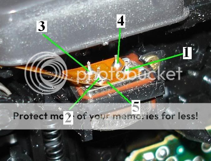
This one is the top view taken off. It looks like "1, 4 and 5" are all connected on the same circuit path as you might be able to tell.
making a noise sniffer -- posted image.
i am an idiot 
Platinum - Posts: 13,666
Platinum spaceThis member consistently provides reliable informationspace
Joined: September 21, 2006
Location: Louisiana, United States
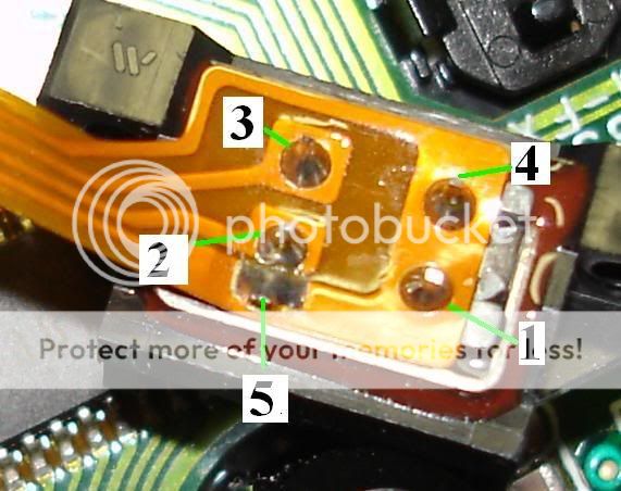
Posted: April 22, 2008 at 3:07 AM / IP Logged  
By a shielded patch cord, I am referring to an RCA cable. A cheap flexible cable would be best for this application. You are correct that 1,4 and 5 are connected together. 1 and 4 are the grounds of the 2 individual heads and 5 is to ground the outer case of the head itself. I have never built one of these, so I do not know if we need to ground the case of the head, or need to leave it ungrounded for greater sensitivity. When soldering the wires back to the head we need to provide a little loop or jumper on the 5th terminal, it needs to be easy to cut in case it needs to be. On the head itself after removing it from the cable, you need to run a jumper from terminal 1 to 3. This will be the wire to series the 2 heads. You need to connect the jumper from 2 to 5, leave enough slack so it can be cut if needed. Connect the center conductor of the RCA cable to 4 on the head. Connect the shield of the cable to 2 which also has the jumper going to 5. Now for the Ribbon cable end. You need to be very careful to not tear the ribbon, You need to find something to mount the RCA cable to so it will not pull on the cable. Pads 2 and 3 of the ribbon cable need to be connected to the center conductor of the RCA cable. The shield of the RCA cable needs to be connected 1 or 4.   That should do it. I started drawing a diagram for you, with your thorough answers so far I am assuming that you will not need the diagram, but if you do just let me know.
i am an idiot 
Platinum - Posts: 13,666
Platinum spaceThis member consistently provides reliable informationspace
Joined: September 21, 2006
Location: Louisiana, United States
Posted: April 22, 2008 at 3:34 AM / IP Logged  
making a noise sniffer -- posted image.
silentblackhat 
Copper - Posts: 138
Copper spacespace
Joined: January 14, 2005
Location: New Brunswick, Austria
Posted: April 22, 2008 at 2:42 PM / IP Logged  
Thanks for the reply. When you refer to the pin numbers on the player head, are they the same exact ones that correspond to the numbered prongs on the picture that i posted? If it does then i am a little confused by the picture made showing the connected RCA cable between the head and the ribbon. On the ribbon the center connector is connected to pics 2 and 3(which i understand) but on the reader head its connected to #4, which is the ground point, but wouldn't the RCAs center be connected to where prongs #2 and #3 on the tape head used to connect to?. I get that the center needs to be connected to 2 and 3 on the ribbon but i am confused why its different on the read head.
basically what im saying is, are we just trying to extend the tape head out from the ribbon kid of like using an extension cord to extend something out like an electrical outlet extension cord? if so, wouldn't connect #2 and #3 together on the ribbon and connect it to #2 and #3 that would be connected together on the read head(this connection being made by the center wire on the RCA). then solder #4 to #4 on the read head using the 'ground' wire on the RCA while soldering a connection between 4, 5 and 1 on the read head so they will all get the ground connection from when i solder #4 from the ribbon to # 4 on the read head.
i am an idiot 
Platinum - Posts: 13,666
Platinum spaceThis member consistently provides reliable informationspace
Joined: September 21, 2006
Location: Louisiana, United States
Posted: April 22, 2008 at 7:58 PM / IP Logged  
We connected the heads in series, to give you more voltage output.  I just used pin 2 as the ground, only reason was that it was next to terminal 5 which is the ground of the case of the head.  Figured it would be easier to put the jumper.  You can try it without running the heads in series, but I really think the extra voltage will be a plus.
jmelton86 
Gold - Posts: 1,228
Gold spacespace
Joined: February 07, 2007
Location: South Carolina, United States
Posted: April 22, 2008 at 8:08 PM / IP Logged  
You can still use the volume control, right? So, the extra voltage will be useful indeed.
2013 Kia Rio -90a alternator
DDX470HD GTO14001 GTO1014D (x3)
Big3 in 1/0G
1/0G to GTO14001
silentblackhat 
Copper - Posts: 138
Copper spacespace
Joined: January 14, 2005
Location: New Brunswick, Austria
Posted: April 22, 2008 at 9:56 PM / IP Logged  
I might be looking at the diagram wrong...The problem I am having is not the picture of the ribbon part but the tape head part; basically i dont get why its connected where it is on the tape head side.
I definitely get that connecting #2 and #3 together and then connecting the center connector to that connection is a good thing on the ribbon. What i don't get is why the tape head part is wired the way it is.
I don't get why #2 and #3 on the tape head aren't connected together with the center conductor of the RCA running to that connection. instead the center conductor from the #2 and #3 connection from the ribbon is connected to #4 on the head which is a ground point. Also #3 is connected to #1 on the tape head where #1 is a ground point. #2 on the tape head is where the RCA's ground wire is connected.
I may be looking at it the wrong way thoughmaking a noise sniffer -- posted image.
i am an idiot 
Platinum - Posts: 13,666
Platinum spaceThis member consistently provides reliable informationspace
Joined: September 21, 2006
Location: Louisiana, United States
Posted: April 22, 2008 at 10:13 PM / IP Logged  
making a noise sniffer -- posted image.
Page of 2

  Printable version Printable version Post ReplyPost New Topic
You cannot post new topics in this forum
You cannot reply to topics in this forum
You cannot delete your posts in this forum
You cannot edit your posts in this forum
You cannot create polls in this forum
You cannot vote in polls in this forum

  •  
Search the12volt.com
Follow the12volt.com Follow the12volt.com on Facebook
Friday, March 29, 2024 • Copyright © 1999-2024 the12volt.com, All Rights Reserved Privacy Policy & Use of Cookies
Disclaimer: *All information on this site ( the12volt.com ) is provided "as is" without any warranty of any kind, either expressed or implied, including but not limited to fitness for a particular use. Any user assumes the entire risk as to the accuracy and use of this information. Please verify all wire colors and diagrams before applying any information.

Secured by Sectigo
the12volt.com spacer
Support the12volt.com
Top
the12volt.com spacer