the12volt.com spacer
icon

Ground Out When Running Wire


Post ReplyPost New Topic
< Prev Topic Next Topic >
MX6boii 
Copper - Posts: 74
Copper spaceThis member has made a donation to the12volt.com. Click here for more info.spacespace
Joined: October 22, 2002
Location: Pennsylvania, United States
Posted: August 15, 2008 at 10:29 PM / IP Logged  
Hi, I'm helping a friend reinstall a remote start system. I've installed a few of these before (Valet+bypasskit) but not frequently enough to remember some details. I'm working with a Valet 561r and bypass module PKH3. This system has been installed professionally the first time.
Luckily through old posts (by me...), I read that the blue Status Output wire in the 4pin satellite harness on the 561r is used to send a (-) output. Perfect for the 'ground out when running' signal to the bypass module. What I don't understand is why DEI does not have any details explaining this particular harness and it's output/input polarity. What's sad is that the "professionals" did not use the 4 pin satellite harness. Instead....
The "professionals" connected the 'ground out when running' wire on the PKH3 to the H2 remote start harness: H2/5 (-) 200mA 2nd status/rear defogger output. I understand this wire will work because it is sending out a (-) output upon remote start. But what if the customer would like this wire connected to run the rear defroster also? Is there a way to do this? Simply connecting both defroster and 'ground out when running' wires together? A relay is another solution but could be going too far because we're not switching anything big in power.
What's even worse is that they didn't install the hood pin switch. Instead connected that wire also to H2/5 for a (-) signal when remote starting to fake a closed hood.
Thanks for your time and knowledge everyone.
hurleyloser 
Copper - Posts: 157
Copper spacespace
Joined: February 05, 2005
Location: California, United States
Posted: August 16, 2008 at 1:08 AM / IP Logged  

im not too familiar with the 561r, but i've done tons of their other remote start systems that have the ribbon harness that goes to the relay xtreme capacity satellite, i typically grab the ground when running from that ribbon harness, this wire is also known as the status output.

the 2nd status/rear defogger wire is programmable to be either 2nd status (can also use this wire instead of the first status for bypasses, but other common uses can be to activate relays to inturrupt other sensors throughout the vehicle so they do not false during remote start. technically, they didn't hook it up incorrectly, unless the customer requested defogger output, in which case they should have used the primary status for the bypass and programmed the 2ndstatus/defogger output to defogger setting and use a relay to connect that to the vehicles deffogger trigger.

do not just connect the 2nd status to both the bypass and the defogger, it's a 200mA output, so very low current as it is. if you split between the two, that's 100mA to the defogger, and 100mA to the bypass. you will run the risk of damaging the output from the alarm. either use a couple of relays to supply ground when running to the bypass and a ground to the defogger trigger in the vehicle, or use the 1st status for the bypass, and program the second for the defogger.

also, please connect the hood trigger, it's there for safety. maybe have him take it back to the original installation shop and have them hook it up.

MECP Master Certified Technician
ASE A6 Certified Technician
MX6boii 
Copper - Posts: 74
Copper spaceThis member has made a donation to the12volt.com. Click here for more info.spacespace
Joined: October 22, 2002
Location: Pennsylvania, United States
Posted: August 18, 2008 at 10:36 AM / IP Logged  
Hey thanks for your input in clearing things up.
These half ass installs some shops do in philly are horrible. I doubt if my friend goes back they'll remember the job and wouldn't replace the missing hood trigger. Of course my friend didn't know anything about the RS system. So they took it upon themselves to wire it using the 2nd status output. I'm guessing they didn't know that the the satellite harness 'status wire' produces a (-) output.
How do you know that the 'status output' on the satellite harness puts out a (-)? If this ribbon harness was given a description like the other harness' I probably wouldn't have run into this problem.
Thanks again. I'm gonna see if I can find the missing parts to correct this install when I put it back in.
hurleyloser 
Copper - Posts: 157
Copper spacespace
Joined: February 05, 2005
Location: California, United States
Posted: August 18, 2008 at 4:46 PM / IP Logged  

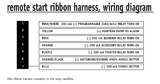
like I've said, I'm very familiar with the directed remote start system since that's the only brand my particular retailer carries for alarms/remote starts. I know that the blue wire on the ribbon produces a (-) status output because it's usually listed in the manual. You can also meter this wire if you're skeptical. Most of the wires in that ribbon harness produce the (-) turn on signals to the relay satellite for their respective functions (i.e. pink-ignition, purple-starter, orange-accessory, etc).

this is the ribbon harness that i'm talking about:

Ground Out When Running Wire -- posted image.

I also looked at the manual for the 561r and the status output on the 4 pin harness you are talking about should also work for the bypass.

MECP Master Certified Technician
ASE A6 Certified Technician
Thack79 
Silver - Posts: 526
Silver spacespace
Joined: December 02, 2003
Location: Virginia, United States
Posted: August 19, 2008 at 7:57 AM / IP Logged  
Whom do you call "Professionals"  ?
MX6boii 
Copper - Posts: 74
Copper spaceThis member has made a donation to the12volt.com. Click here for more info.spacespace
Joined: October 22, 2002
Location: Pennsylvania, United States
Posted: August 19, 2008 at 2:54 PM / IP Logged  
Hurleyloser:
Hey, I'm not doubting you one bit that the satellite ribbon harness produces a (-) output on the status wire and others also. If DEI was as detailed on the satellite harness as your pic, I wouldn't be asking this question. That's what I've been complaining about. The 561r manual has descriptions of every harness BUT the satellite harness. The older DEI remote starters I've installed I never ran into this problem.
So...if I wanted to meter the satellite ribbon harness, I'm guessing I would have to put the key into the key cylinder and meter the status wire, turn the key to ACC and meter the ACC trigger wire, etc...?
The whole point of this post was to learn something and understand a little more in depth about this DEI product.
Once again...THANKS for you input.
Thack79:
I was talking about the original installers of this system, but I meant it sarcastically. How can I call them professionals if they half assed everything. The only thing that made the install look good was the black wire loom that hid all the wires.
megaman 
Copper - Posts: 385
Copper spacespace
Joined: June 24, 2008
Location: Montana, United States
Posted: August 19, 2008 at 3:32 PM / IP Logged  

At first I was thinking "what is this guy talking about, they always show what wire is what?!?"  Then I looked up the manual for the 561r and looked into it.  They show the harness listed as the 4-pin satellite harness and give brief descriptions as to what each wire is for, but they don't list polarity.  And in the manual the harness is not listed or given a description for it. 

This is what we call bad technical writing and proof reading.

You probably already figured it out, but all 4 wires are (-) trigger output.

Blue :  (-)status, ground when running output

Orange : (-)Accessory output.  Gives a ground when the remote start accessory output is active

Purple : (-)Starter output. Ground output when starter from Remote Start is active

Pink : (-) Ignition output.  Gives ground when the remote start Ignition output is active.

hurleyloser 
Copper - Posts: 157
Copper spacespace
Joined: February 05, 2005
Location: California, United States
Posted: August 19, 2008 at 3:43 PM / IP Logged  

MX6boii,

not exactly, to meter the ribbon harness, it should only provide the low current trigger when ever the remote start is engaging that particular function for the signal, so it will only have a (-) trigger present on the status wire when you engage remote start mode, and throughout the remote start process. It will only show (-) trigger on the acc (orange) when the remote start is turning on the accessory circuits and while they remain on, it will only show (-) on the pink wire when the remote start is turning on the ignition circuits, etc...

so status should show (-) from the moment you begin the remote start process till the moment you perform take over

acc will show (-) when the remote start is activiated and simulates a single key turn to the acc position, but will drop during the cranking process
ign should show (-) when the remote start simulates the key in the second position and turns the ignition circuits on
start should show (-) during crank only

you can test these buy placing the positive probe of your meter to a constant 12v source, and probing the wire you are testing with the negative probe.

remember the status wire should provide a (-) during the entire remote start process, from initialization to take over. This will ensure that a bypass module will be turned on the entire time during remote start.

MECP Master Certified Technician
ASE A6 Certified Technician
MX6boii 
Copper - Posts: 74
Copper spaceThis member has made a donation to the12volt.com. Click here for more info.spacespace
Joined: October 22, 2002
Location: Pennsylvania, United States
Posted: August 19, 2008 at 4:09 PM / IP Logged  
That helped a lot guys!
Thanks.

Sorry, you can NOT post a reply.
This topic is closed.

  Printable version Printable version Post ReplyPost New Topic
You cannot post new topics in this forum
You cannot reply to topics in this forum
You cannot delete your posts in this forum
You cannot edit your posts in this forum
You cannot create polls in this forum
You cannot vote in polls in this forum

  •  
Search the12volt.com
Follow the12volt.com Follow the12volt.com on Facebook
Thursday, March 28, 2024 • Copyright © 1999-2024 the12volt.com, All Rights Reserved Privacy Policy & Use of Cookies
Disclaimer: *All information on this site ( the12volt.com ) is provided "as is" without any warranty of any kind, either expressed or implied, including but not limited to fitness for a particular use. Any user assumes the entire risk as to the accuracy and use of this information. Please verify all wire colors and diagrams before applying any information.

Secured by Sectigo
the12volt.com spacer
Support the12volt.com
Top
the12volt.com spacer