the12volt.com spacer
icon

street rod power lock needed


Post ReplyPost New Topic
< Prev Topic Next Topic >
1936fordturbo 
Member - Posts: 10
Member spacespace
Joined: September 19, 2008
Location: Ohio, United States
Posted: September 19, 2008 at 8:03 AM / IP Logged  
Hello, any help will be greatly appreciated. Installing a Viper 5002 in my 36 Ford Street Rod. I have 2 aftermarket two wire lock actuators. I originally wired one actuator by using diagram D shown for aftermarket actuators (violet to 12+, white & brown to ground, green & blue wire from alarm to actuators) and lock seam to work fine. I than proceeded to add the other door and than some happened where it worked a few times and then nothing. Did I fry something or does this have to be hooked up an other way?
Thanks, Dave
i am an idiot 
Platinum - Posts: 13,671
Platinum spaceThis member consistently provides reliable informationspace
Joined: September 21, 2006
Location: Louisiana, United States
Posted: September 19, 2008 at 11:20 AM / IP Logged  
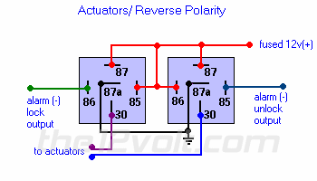
Actuators / Reverse Polarity
This is practically identical to the 5 wire alternating 12V(+) system above. The only difference is there's no switch! Both motor legs rest at ground at the relays. To lock or unlock the vehicle, polarity is changed on one motor leg.
 
street rod power lock needed -- posted image.
1936fordturbo 
Member - Posts: 10
Member spacespace
Joined: September 19, 2008
Location: Ohio, United States
Posted: September 19, 2008 at 2:56 PM / IP Logged  
Thank You, that looks easy enough. How do I add a interior switch to this?
Dave
i am an idiot 
Platinum - Posts: 13,671
Platinum spaceThis member consistently provides reliable informationspace
Joined: September 21, 2006
Location: Louisiana, United States
Posted: September 19, 2008 at 6:28 PM / IP Logged  

See the 2 connections that say alarm unlock output and alarm lock output?  Simply ground the appropriate wire via a momentary On-Off-On rocker switch.  Simply ground the middle terminal of the switch and connect one switch terminal to the alarm lock output wire, this will lock the doors.  The other terminal of the switch connects to the alarm unlock output wire this will unlock the doors.

1936fordturbo 
Member - Posts: 10
Member spacespace
Joined: September 19, 2008
Location: Ohio, United States
Posted: September 21, 2008 at 10:50 AM / IP Logged  

Thanks again, I will give it a try. By the way, Your no Idiot. street rod power lock needed -- posted image.

Thank You, Dave

1936fordturbo 
Member - Posts: 10
Member spacespace
Joined: September 19, 2008
Location: Ohio, United States
Posted: October 19, 2008 at 9:06 AM / IP Logged  
Hello, I need some more help. The above relay diagram works great, however the relays being energized kills the battery when car sits for a couple of weeks with out being started. Is there a way to fix this problem?
Thanks again, Dave
i am an idiot 
Platinum - Posts: 13,671
Platinum spaceThis member consistently provides reliable informationspace
Joined: September 21, 2006
Location: Louisiana, United States
Posted: October 19, 2008 at 10:27 AM / IP Logged  
The relays are only energized when you locking or unlocking the doors.  when energized they pull 160 Milliamps of current each, they only energize one relay at a time.  If one of them was staying energized, this would run your battery down in a couple of days, unless of course your streetrod has a bank of about 10 batteries.    I am sure that it is the alarm system that is running the battery down.  Even disarmed they do pull a little current, most vehicles are driven daily or at the minimum once a week or so.  The reciever inside the brain has to run so it can look for signals from the remote.
KarTuneMan 
Platinum - Posts: 7,056
Platinum spaceThis member has made a donation to the12volt.com. Click here for more info.spaceThis member consistently provides reliable informationspace
Joined: December 14, 2004
Location: Isle Of Man
Posted: October 21, 2008 at 1:32 AM / IP Logged  

1936fordturbo wrote:
Hello, I need some more help. The above relay diagram works great, however the relays being energized kills the battery when car sits for a couple of weeks with out being started. Is there a way to fix this problem?
Thanks again, Dave

This should not happen. If the relay is staying activated (latched) there is an error in the wireing.

Understanding "how" a relay works will give you all of the answers you need.

i am an idiot 
Platinum - Posts: 13,671
Platinum spaceThis member consistently provides reliable informationspace
Joined: September 21, 2006
Location: Louisiana, United States
Posted: October 21, 2008 at 5:01 AM / IP Logged  
He was thinking that the relays were running his battery down. It takes 3 weeks or so to run it down. I was just telling him that if the relays WERE pulling current, the 160MA of the relay would run it down in a matter of days. That is not even taking into consideration the amount of current the actuators would be pulling.
1936fordturbo 
Member - Posts: 10
Member spacespace
Joined: September 19, 2008
Location: Ohio, United States
Posted: October 22, 2008 at 1:31 PM / IP Logged  
Yes, when I put 12 volts to the relays they click and stay energized. I believe this is what is draining the battery. How do i fix this problem?
Dave
Page of 2

  Printable version Printable version Post ReplyPost New Topic
You cannot post new topics in this forum
You cannot reply to topics in this forum
You cannot delete your posts in this forum
You cannot edit your posts in this forum
You cannot create polls in this forum
You cannot vote in polls in this forum

  •  
Search the12volt.com
Follow the12volt.com Follow the12volt.com on Facebook
Friday, May 10, 2024 • Copyright © 1999-2024 the12volt.com, All Rights Reserved Privacy Policy & Use of Cookies
Disclaimer: *All information on this site ( the12volt.com ) is provided "as is" without any warranty of any kind, either expressed or implied, including but not limited to fitness for a particular use. Any user assumes the entire risk as to the accuracy and use of this information. Please verify all wire colors and diagrams before applying any information.

Secured by Sectigo
the12volt.com spacer
Support the12volt.com
Top
the12volt.com spacer