Posted: January 23, 2009 at 5:00 PM / IP Logged
Posted: January 24, 2009 at 11:57 AM / IP Logged
Sorry, you can NOT post a reply.
This topic is closed.
 Printable version


| You cannot post new topics in this forum You cannot reply to topics in this forum You cannot delete your posts in this forum You cannot edit your posts in this forum You cannot create polls in this forum You cannot vote in polls in this forum |

| Search the12volt.com |
Follow the12volt.com 
Friday, January 9, 2026 • Copyright © 1999-2026 the12volt.com, All Rights Reserved • Privacy Policy & Use of Cookies


Friday, January 9, 2026 • Copyright © 1999-2026 the12volt.com, All Rights Reserved • Privacy Policy & Use of Cookies
Disclaimer:
*All information on this site ( the12volt.com ) is provided "as is" without any warranty of any kind, either expressed or implied, including but not limited to fitness for a particular use. Any user assumes the entire risk as to the accuracy and use of this information. Please
verify all wire colors and diagrams before applying any information.


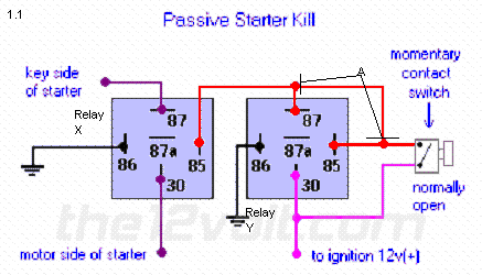
 I have labeled the relay's X and Y. And 1 wire labeled A.
My questions are:
What is the purpose of wire A? When the momentary switch is pressed the circuit from 30 to 87 is made providing voltage to the connector at 30. It seems to me that wire A makes the relay rather pointless as wire A would provide voltage when the momentary switch is pressed.
Second Question, Is relay y even needed? Would you not achieve the same result by simply connecting a momentary switch between voltage and the 85 connector of relay X?
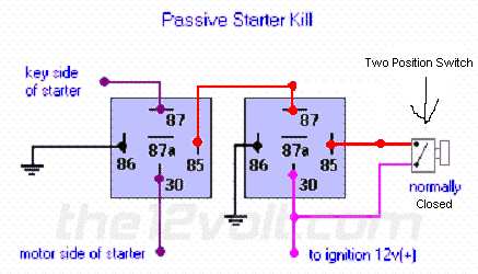
Also, The kill switch I am hoping to use is actually a two position switch, allowing me to leave the kill switch disabled so I don't have to press a button every time to start it. Example, running to the store, having to stop my car to change a tire. I would like to be able to enable the kill switch when the car is going to be parked for a longer period of time etc. Would this diagram achieve what I am looking to do?


