the12volt.com spacer
icon

resistors burning up my leds


Post ReplyPost New Topic
< Prev Topic Next Topic >
KPierson 
Platinum - Posts: 3,527
Platinum spaceThis member consistently provides reliable informationspace
Joined: April 14, 2005
Location: Ohio, United States
Posted: March 31, 2009 at 3:06 PM / IP Logged  

Pot is short for potentiometer - they are adjustable resistors.

a 10K pot would be adjustable from 0ohm to 10,000 ohm.  You need to be careful when adjusting the pot though, because if you go below that 500 ohm mark you could damage the LED - to be "safe" you can hook the 470 ohm resistor in series with the pot - this will give you a 470 - 10,470 ohm range so you will never have to worry about putting too much current to the LED.

The pot will have three terminals on it - two outside terminals and a middle terminal.  You would only need two terminals, one of the outside terminals and the middle terminal.

So, basically to find the resistance you would hook your 470ohm resistor to battery power (while the bike is on and the battery is charging).  Wire the other side of the reisistor to one of the outside legs on the pot.  Wire the middle leg to the + terminal of the LED (the longer leg).  Wire the shorter leg to ground.  Now, adjust the knob/dial/etc on the pot to the desired brightness (don't look directly at the LED - super bright isn't just a clever name).  Once you have it dialed in you can remove the circuit from the bike and measure the resistance between the outside leg you used and the middle leg.  Add 470 to that value to accomidate for the 470 ohm resistor and that is the value of the resistor you need for that brightness.

If you want to get fancy (which seriously seems like overkill here) you could install a 5vdc regulator and run the LED off of it.  The regulator will keep the voltage at a rock solid 5vdc so the LED won't vary in brightness as the battery voltage goes up and down.  However, for an idiot light, that probably isn't needed at all!

Kevin Pierson
i am an idiot 
Platinum - Posts: 13,668
Platinum spaceThis member consistently provides reliable informationspace
Joined: September 21, 2006
Location: Louisiana, United States
Posted: March 31, 2009 at 5:05 PM / IP Logged  

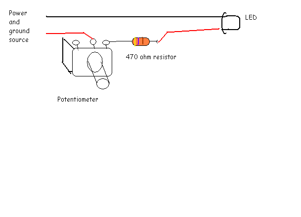
I figured that since you did not know what a pot was, you might need a little help with the installation of said pot.

resistors burning up my leds - Page 2 -- posted image.

I drew it backwards, CCW will be full brightness.  CW will be the dimmest possible.

rfhelp 
Member - Posts: 31
Member spacespace
Joined: March 23, 2009
Location: British Columbia, Canada
Posted: March 31, 2009 at 5:45 PM / IP Logged  
KPierson wrote:

So, basically to find the resistance you would hook your 470ohm resistor to battery power (while the bike is on and the battery is charging).  Wire the other side of the reisistor to one of the outside legs on the pot.  Wire the middle leg to the + terminal of the LED (the longer leg).  Wire the shorter leg to ground. 

Kevin, is the above statment the same as the diagram? you said to connect the resistor to bat power and  the outside terminal. then the long lead of the led to the middle termininal but that is I think going to power in the diagram and the anode to ground.

In my head red is positive/black is ground. Buddy at the shop told me the center terminal is a ground terminal.

KPierson 
Platinum - Posts: 3,527
Platinum spaceThis member consistently provides reliable informationspace
Joined: April 14, 2005
Location: Ohio, United States
Posted: March 31, 2009 at 6:00 PM / IP Logged  

The posted picture will work, too.

The pot has no polarity so there is no power or ground terminals.  As long as all the components are hooked up it should work.  The only thing you need to pay attention to is the polarity of the LED.

In fact, the resistors can be installed on the ground side of the LED and the positive side can be hooked stright to the battery and it will still work.  The resistance just needs to be somewhere between the battery and ground to limit the current flowing in the circuit.

Kevin Pierson
Page of 2

Sorry, you can NOT post a reply.
This topic is closed.

  Printable version Printable version Post ReplyPost New Topic
You cannot post new topics in this forum
You cannot reply to topics in this forum
You cannot delete your posts in this forum
You cannot edit your posts in this forum
You cannot create polls in this forum
You cannot vote in polls in this forum

  •  
Search the12volt.com
Follow the12volt.com Follow the12volt.com on Facebook
Tuesday, April 30, 2024 • Copyright © 1999-2024 the12volt.com, All Rights Reserved Privacy Policy & Use of Cookies
Disclaimer: *All information on this site ( the12volt.com ) is provided "as is" without any warranty of any kind, either expressed or implied, including but not limited to fitness for a particular use. Any user assumes the entire risk as to the accuracy and use of this information. Please verify all wire colors and diagrams before applying any information.

Secured by Sectigo
the12volt.com spacer
Support the12volt.com
Top
the12volt.com spacer