the12volt.com spacer
icon

best way to reverse polarity on solenoid


Post ReplyPost New Topic
< Prev Topic Next Topic >
KPierson 
Platinum - Posts: 3,527
Platinum spaceThis member consistently provides reliable informationspace
Joined: April 14, 2005
Location: Ohio, United States
Posted: April 22, 2009 at 11:30 AM / IP Logged  

i am an idiot wrote:
If your controller will trigger a 5V relay with I think .090 amps of current.  This will be simple with 2 relays.  But you will have to use 2 ports  one to latch to A and another to latch to B. 

I, personally, wouldn't drive anything over 0.020A directly off of a uC pin.  You would also need diodes across the coil of the relays.  About the only thing I would ever consider running directly is either a reed relay or an LED, anything else, generally, needs an amplifier.

Kevin Pierson
fisherangel7 
Member - Posts: 21
Member spacespace
Joined: April 20, 2009
Posted: April 22, 2009 at 6:11 PM / IP Logged  

Hey KPierson,  neat idea.  Can you provide a schematic.. that might solve alot of problems with limited ports available.  I think mosfets use actually very nearly 0 current when just sitting there.   The idea is to not use any power anywhere in the whole circuit after xx latching solenoid is latched up.    Using intermediate relays means that they remain in some position that is passing power to the xx solenoid even though their own control power may be off.     I would say that an all mosfet transistor setup would be least power using in the idle state.

THANKS if you can provide complete detailed schematic.. thanks

In Name of Jesus Christ = Peace (not war) Amen.

The MUC pins are rated for 20ma but Total is higher for all pins (but not 20 ma each all at same time.. ie if you have 20 pins.. its not 400ma total.. probably more like 70ma total so of course we want the pulse type system.

i am an idiot 
Platinum - Posts: 13,670
Platinum spaceThis member consistently provides reliable informationspace
Joined: September 21, 2006
Location: Louisiana, United States
Posted: April 22, 2009 at 8:09 PM / IP Logged  
Does this controller output ground or 5volts?   I think I can make it happen with 2 transistors 2 diodes 2 SCRs 2 half wave rectifiers, 6 capacitors, and I can even throw in a requested FET.    It isn't going to take all of the above parts, only the transistors diodes and relays. Do you have a datasheet on your controller, I can integrate the controller into my diagram.    And you also never answered the question about any more twists.
KPierson 
Platinum - Posts: 3,527
Platinum spaceThis member consistently provides reliable informationspace
Joined: April 14, 2005
Location: Ohio, United States
Posted: April 22, 2009 at 9:27 PM / IP Logged  

I think the issue here is you really have no idea what you want, or what you need, and therefore don't understand any of the options given to you.

The relays in my suggestion would just be pulsed on and off.  They wouldn't stay latched.  They are ONLY there to reverse the polarity.  The solenoid latches on its own, based on the information you gave us.

I don't see a need to draw up a schematic, maybe someone else will.  It's a VERY basic circuit and you should be able to find them on the internet (do a google search for 'transistorised relay driver'.  You'll need one NPN circuit and one PNP circuit all driven off the same output pin.

I, personally, would go with the multiple transistors and just size the output transistors appropriately for the solenoid you are using.  You may even be able to find an H bridge chip that is compatible with your uC and lower your parts count.

What exactly is this project for?  Typically, when people start messing around with microcontrollers they have at least a basic electronic knowledge and a circuit like this wouldn't be an issue.  Is this like a school project or something?

Kevin Pierson
fisherangel7 
Member - Posts: 21
Member spacespace
Joined: April 20, 2009
Posted: April 22, 2009 at 9:35 PM / IP Logged  

Ok.. then since you are so clever, how then do you have a relay providing a reversing polarity to the big xx solenoid and that same relay completely unpowered on either control side or power thru contacts side when pulse is not coming thru.  We know it could probably be worked out with mosfets.. but we were hoping some good guru  had already perfected.  I guess we were looking for someone who does it for a living and is up on the subject and could just zap out a schematic.  Obviously its beyond your abilities  or   Probably you don't know???

Also just because someone asks the time of day doesn't they can't tell time.  If you are going to arrogant, please do it on your own time. thanks.

Leggo your ego !

In the Name of Jesus Christ = Peace (not war). amen!

fisherangel7 
Member - Posts: 21
Member spacespace
Joined: April 20, 2009
Posted: April 22, 2009 at 9:43 PM / IP Logged  
if anyone can post a complete schematic of a one pulse system to reverse polarity to latch a 100 amp 72 volt latching solenoid "without" using any control power or any other power except when activating the pulse, please post.. All sincere entries appreciated. thanks!
KPierson 
Platinum - Posts: 3,527
Platinum spaceThis member consistently provides reliable informationspace
Joined: April 14, 2005
Location: Ohio, United States
Posted: April 22, 2009 at 10:07 PM / IP Logged  
fisherangel7 wrote:

Also just because someone asks the time of day doesn't they can't tell time.  If you are going to arrogant, please do it on your own time. thanks.

I appologize if you think I'm being arrogent, I just don't understand how you're going to program a microcontroller, download the program, power it, and run your solenoid if you can't figure this simple circuit out.  I posted a fairly detailed description of how it works, yet it wasn't enough for you to figure out.  I appologize that I am unwilling to spend 30 minutes drawing up a diagram that you should be able to figure out from my description.  To me, it seems like you have a group project for school or something and this is your "part" of the assignment.  I could be wrong, but thats what it seems like.

fisherangel7 wrote:
Ok.. then since you are so clever, how then do you have a relay providing a reversing polarity to the big xx solenoid and that same relay completely unpowered on either control side or power thru contacts side when pulse is not coming thru.  We know it could probably be worked out with mosfets.. but we were hoping some good guru  had already perfected.  I guess we were looking for someone who does it for a living and is up on the subject and could just zap out a schematic.  Obviously its beyond your abilities  or   Probably you don't know???

OK, I'm not sure how else to explain this so you understand.  You already posted:

fisherangel7 wrote:

Best way to Reverse Both + and - on a solenoid?

I have solenoid that is latching type single coil SPDT .  I need to reverse the polarity with one pulse in either direction to cause it to switch from position A to position B and vice versa/  WHat is best way to do it with 12 relays lowest parts count.. thanks.

So, I'm assuming all you need is the ability to provide REVERSE POLARITY pulses to the solenoid in question.  You went a step further to add that you want it done off of one output pin (not port like you keep calling it, a port is a group of pins).  This can EASILY be done with two SPDT relays in a typical "five wire" configuration.  The NC pins of BOTH relays rest at ground and the NO pins are connected to 12vdc.  So, normally, the solenoid has a ground on BOTH wires (and therefore no current flows).  When you fire ONE relay it removes a ground from the solenod and replaces it with voltage.  This creates a REVERSE POLARITY PULSE to pulse the solenoid you mentioned above.  When you return your output pin to a high impedence state the relay will shut off, and NO CURRENT will flow through any parts.  The solenoid will stay latched because YOU said it was a latching solenoid. 

Mosfets will work, but are overkill and are very sensitive.  They should only be used when you need a very low on resistance (to minimize heat) or if you need high speeds - you need neither here.  I would go with NPN and PNP transistors that are pretty much bullet proof for your application.

Do you have any idea how much current your solenoid is going to require to pull in?  The amount of current needed to energize the solenoid will ultimately determine the "best" way to do what you are trying to do.

Kevin Pierson
fisherangel7 
Member - Posts: 21
Member spacespace
Joined: April 20, 2009
Posted: April 22, 2009 at 10:20 PM / IP Logged  

Ok kevin,

I am very tied up with doing software so any drawn schematic would be nice just to clarify it for our reference.   Can you scratch out a complete schematic.  I have one pin available (out of 35 ) to do this with, it can provide 20 ma @ ~ 5v.   I think your idea makes sense but would again be nice to see it all drawn out completely.   Just use Paint program and don't worry if its pretty (ugly is great as long as remotely readable and completely understandable).   Yeah we could probably work it out.. but you already know it all as its your idea.   I must say I am intriqued to be able to have 0 power used except when changin the position of the final xx solenoid .  so ,  Thanks.

It takes 10 to dance the binary!   

KPierson 
Platinum - Posts: 3,527
Platinum spaceThis member consistently provides reliable informationspace
Joined: April 14, 2005
Location: Ohio, United States
Posted: April 22, 2009 at 10:38 PM / IP Logged  

Again, google is your friend.

best way to reverse polarity on solenoid - Page 4 -- posted image.

(taken from a site I found on Google).

Connect your output pin to the "control" dot.  R2 is optional in both diagrams and as long as you use quality components you shouldn't need either one of them.

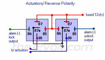
Next, use this diagram from this site:

best way to reverse polarity on solenoid - Page 4 -- posted image.

You'll have to modify it slightly:

Left relay:

Pin 86 - connect where the relay goes on the left diagram above (positive logic diagram).

Everything else is as shown

Right relay:

Pin 86 - connect directly to ground
Pin 85 - connect where the relay goes on the right diagram above (negative logic diagram).

Pin 30 on both relays will connect to one side each of the solenoid.

Kevin Pierson
i am an idiot 
Platinum - Posts: 13,670
Platinum spaceThis member consistently provides reliable informationspace
Joined: September 21, 2006
Location: Louisiana, United States
Posted: April 22, 2009 at 11:44 PM / IP Logged  
That is exactly how I was going to wire the relays. But I was going to use 5 volt relays and have a transistor as current gain amplifier. But I am afraid that after I draw it up there will be another twist.
Page of 5

  Printable version Printable version Post ReplyPost New Topic
You cannot post new topics in this forum
You cannot reply to topics in this forum
You cannot delete your posts in this forum
You cannot edit your posts in this forum
You cannot create polls in this forum
You cannot vote in polls in this forum

  •  
Search the12volt.com
Follow the12volt.com Follow the12volt.com on Facebook
Wednesday, May 1, 2024 • Copyright © 1999-2024 the12volt.com, All Rights Reserved Privacy Policy & Use of Cookies
Disclaimer: *All information on this site ( the12volt.com ) is provided "as is" without any warranty of any kind, either expressed or implied, including but not limited to fitness for a particular use. Any user assumes the entire risk as to the accuracy and use of this information. Please verify all wire colors and diagrams before applying any information.

Secured by Sectigo
the12volt.com spacer
Support the12volt.com
Top
the12volt.com spacer