the12volt.com spacer
icon

wiring up thermo fan spdt relay


Post ReplyPost New Topic
< Prev Topic Next Topic >
evo180sx 
Member - Posts: 13
Member spacespace
Joined: May 03, 2009
Location: Australia
Posted: May 03, 2009 at 9:49 PM / IP Logged  
ok no problem :),
Also in your diagram....I want to add in a manual switch inside the cabin of the car.
What would I need to do?
thanks
michael
evo180sx 
Member - Posts: 13
Member spacespace
Joined: May 03, 2009
Location: Australia
Posted: May 04, 2009 at 4:46 AM / IP Logged  
its working fine now :D
thanks alot for that!
would you know the above question though?
thanks
i am an idiot 
Platinum - Posts: 13,720
Platinum spaceThis member consistently provides reliable informationspace
Joined: September 21, 2006
Location: Louisiana, United States
Posted: May 04, 2009 at 9:10 AM / IP Logged  
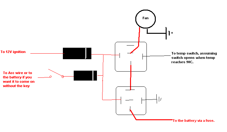
I will post a picture tonight.  It requires (2) 1N4001 diodes available at Radio Shack.  Attach both diodes to the point that now says 12V Ignition, with the banded end of the diode nearest the relays.  Non Banded end of one goes to 12V ignition.  Non Banded end of the other diode goes to your switch.  Other terminal of the switch goes to Acc wire or to the battery.  Place a 3 amp fuse at the point of connection.   If you run it to Acc, it will only come on with key in acc position.  If you run it to the battery, it can come on anytime the switch is turned on.
i am an idiot 
Platinum - Posts: 13,720
Platinum spaceThis member consistently provides reliable informationspace
Joined: September 21, 2006
Location: Louisiana, United States
Posted: May 04, 2009 at 3:25 PM / IP Logged  
wiring up thermo fan spdt relay - Page 2 -- posted image.
evo180sx 
Member - Posts: 13
Member spacespace
Joined: May 03, 2009
Location: Australia
Posted: August 04, 2009 at 5:11 AM / IP Logged  
hey guys,
Im back! I recently just purchased a new thermo switch which turns the fan on a slightly lower temp.
Its the same connection on the switch except its a Normally Open Ground instead.
Im thinking all I have to do to my current wiring is put the Positive wiring from the Fan to 87 instead of 87a.
Is this correct.
thanks in advance.
i am an idiot 
Platinum - Posts: 13,720
Platinum spaceThis member consistently provides reliable informationspace
Joined: September 21, 2006
Location: Louisiana, United States
Posted: August 04, 2009 at 7:43 AM / IP Logged  

Yes you will need to use 87 instead of 87A on the top relay.  However you will lose the ability of the switch unless the temp is above the threashhold of the switch. 

Let's Go Brandon Brown. Congratulations on your first Xfinity Series Win. LGBFJB
evo180sx 
Member - Posts: 13
Member spacespace
Joined: May 03, 2009
Location: Australia
Posted: August 04, 2009 at 5:05 PM / IP Logged  
No worries,
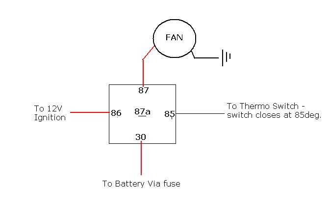
I have changed it over to 87 and drove the car to around the 91 degree mark and the fan did not come on....I have the same wiring as before but I never connected the switch up as I didnt think it was nessesory.
Any tips? and also with this setup could i run it like this?
wiring up thermo fan spdt relay - Page 2 -- posted image.
i am an idiot 
Platinum - Posts: 13,720
Platinum spaceThis member consistently provides reliable informationspace
Joined: September 21, 2006
Location: Louisiana, United States
Posted: August 04, 2009 at 9:31 PM / IP Logged  
if you are sure you have 12 volts on the ignition wire and on 30, there is a problem with the temp sensor. or the relay.
Let's Go Brandon Brown. Congratulations on your first Xfinity Series Win. LGBFJB
evo180sx 
Member - Posts: 13
Member spacespace
Joined: May 03, 2009
Location: Australia
Posted: August 04, 2009 at 11:07 PM / IP Logged  
no worries i will have a look...
can I run the relay with the above diagram or will it cause any issues?
cheers
evo180sx 
Member - Posts: 13
Member spacespace
Joined: May 03, 2009
Location: Australia
Posted: August 04, 2009 at 11:09 PM / IP Logged  
evo180sx wrote:
no worries i will have a look...
can I run the relay with the above diagram or will it cause any issues?
cheers
also the Temp sensor is brand new...and the relays were working yesterday...if there was a problem with the relays it wouldnt be able to work with the old diagram?
Page of 3

  Printable version Printable version Post ReplyPost New Topic
You cannot post new topics in this forum
You cannot reply to topics in this forum
You cannot delete your posts in this forum
You cannot edit your posts in this forum
You cannot create polls in this forum
You cannot vote in polls in this forum

  •  
Search the12volt.com
Follow the12volt.com Follow the12volt.com on Facebook
Monday, September 15, 2025 • Copyright © 1999-2025 the12volt.com, All Rights Reserved Privacy Policy & Use of Cookies
Disclaimer: *All information on this site ( the12volt.com ) is provided "as is" without any warranty of any kind, either expressed or implied, including but not limited to fitness for a particular use. Any user assumes the entire risk as to the accuracy and use of this information. Please verify all wire colors and diagrams before applying any information.

Secured by Sectigo
the12volt.com spacer
Support the12volt.com
Top
the12volt.com spacer