the12volt.com spacer
icon

dual electric fan


Post ReplyPost New Topic
< Prev Topic Next Topic >
ga_goosh 
Member - Posts: 20
Member spacespace
Joined: April 29, 2009
Location: Texas, United States
Posted: June 08, 2009 at 7:25 PM / IP Logged  
i have a car that does not originally have electric fans, and the ac has been removed. i have found a way to install a temp switch on the radiator from a different car. i found an e-fan that has 2 fans and cover the radiator completely. i want it to run in a series curcuit for low noise output but to switch to parallel circuit if it needs more coolong power. will i need 2 thermo switches rated at different temps? is there a temp switch that has dual temp switches in 1? i also dont know how to run the relays to obtain this. can i get a scematic of something like this?  thanks for any help offered dual electric fan -- posted image.
i am an idiot 
Platinum - Posts: 13,667
Platinum spaceThis member consistently provides reliable informationspace
Joined: September 21, 2006
Location: Louisiana, United States
Posted: June 08, 2009 at 7:39 PM / IP Logged  

Have you wired the fans in series yet to see if they turn fast enough to do any good? 

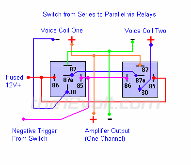
dual electric fan -- posted image.
Amplifier Output = Battery and ground.   Voice Coil one = fan 1   Voice coil two = fan 2    Negative trigger from switch = output of highest temperature sensor.
 
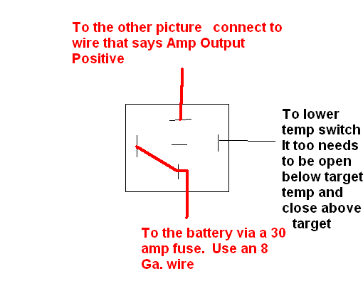
You will have to wire another relay to the other temp sensor that will apply power to the 2 relays when the temp trips that sensor.  Let me know if you need a pic of that too.
ga_goosh 
Member - Posts: 20
Member spacespace
Joined: April 29, 2009
Location: Texas, United States
Posted: June 08, 2009 at 8:00 PM / IP Logged  
i am an idiot wrote:

Have you wired the fans in series yet to see if they turn fast enough to do any good?


no i havent checked yet i will need to see if it is even enough to work. the fans are coming off of a MR2 84-89. i am not sure but it might do this for the ac fan in stock form. i will have to check

i am an idiot wrote:

You will have to wire another relay to the other temp sensor that will apply power to the 2 relays when the temp trips that sensor.  Let me know if you need a pic of that too.

yes i will need a pic of that too thanks

also is the fan switch in this scematic normally open or closed? i forgot to mention this but the temp switch that is coming from the doner car is a 1 wire switch to ground that is normaly grounded and opens when it is at temp. but i can source one that has 2 wires and is normally open. for ease of wiring. thanks

i am an idiot 
Platinum - Posts: 13,667
Platinum spaceThis member consistently provides reliable informationspace
Joined: September 21, 2006
Location: Louisiana, United States
Posted: June 08, 2009 at 8:11 PM / IP Logged  

Ideally you could use a one wire sensor that is open at low temp and would close when target temp is reached.    With that type of switch, the posted diagram will work.  If you can not find a switch like that, I can modify it to make it work.  

dual electric fan -- posted image.

ga_goosh 
Member - Posts: 20
Member spacespace
Joined: April 29, 2009
Location: Texas, United States
Posted: June 08, 2009 at 8:34 PM / IP Logged  
i am an idiot wrote:

Ideally you could use a one wire sensor that is open at low temp and would close when target temp is reached.    With that type of switch, the posted diagram will work.  If you can not find a switch like that, I can modify it to make it work.  

wouldnt it be on in series all the time that way, and parallel when target temp is achieved (if it ever gets there) meaning the fans will always be on if the car is on? i would like it to turn off if the engine is at or below running temp.

as for the switch i dont know exactly what switch to get yet. i do know it comes from a hyundi tho.

if you can modify for the origional switch that would be great. i am not opposed to using 2 thermo switches rated at different temps. lets say one at 190 and the other at 210

i am an idiot 
Platinum - Posts: 13,667
Platinum spaceThis member consistently provides reliable informationspace
Joined: September 21, 2006
Location: Louisiana, United States
Posted: June 08, 2009 at 8:46 PM / IP Logged  

The second diagram kills power to the entire first diagram.  The 2 relays of the first diagram will not get any power until the second diagram feeds power to them.

I will modify the top pic tomorrow.

ga_goosh 
Member - Posts: 20
Member spacespace
Joined: April 29, 2009
Location: Texas, United States
Posted: June 08, 2009 at 8:59 PM / IP Logged  

is this how it is supposed to go?

dual electric fan -- posted image.

i am an idiot 
Platinum - Posts: 13,667
Platinum spaceThis member consistently provides reliable informationspace
Joined: September 21, 2006
Location: Louisiana, United States
Posted: June 08, 2009 at 9:13 PM / IP Logged  
Yes that is how it is supposed to go.  Only thing is, it will pull near 30 amps of current.  You may not want to power this with an ignition circuit.
ga_goosh 
Member - Posts: 20
Member spacespace
Joined: April 29, 2009
Location: Texas, United States
Posted: June 08, 2009 at 9:18 PM / IP Logged  
ok so then i can use a standard 4 pole normally open relay so it will be switched by ignition?
i am an idiot 
Platinum - Posts: 13,667
Platinum spaceThis member consistently provides reliable informationspace
Joined: September 21, 2006
Location: Louisiana, United States
Posted: June 08, 2009 at 9:24 PM / IP Logged  
Correct.  The 2 relays at top of the pic need to be 5 pole.  The other 2 can be of the 4 pole type.   Pole = connections   Do not go asking for a 4 pole relay.   It will have way too many connections.
Page of 5

  Printable version Printable version Post ReplyPost New Topic
You cannot post new topics in this forum
You cannot reply to topics in this forum
You cannot delete your posts in this forum
You cannot edit your posts in this forum
You cannot create polls in this forum
You cannot vote in polls in this forum

  •  
Search the12volt.com
Follow the12volt.com Follow the12volt.com on Facebook
Friday, April 26, 2024 • Copyright © 1999-2024 the12volt.com, All Rights Reserved Privacy Policy & Use of Cookies
Disclaimer: *All information on this site ( the12volt.com ) is provided "as is" without any warranty of any kind, either expressed or implied, including but not limited to fitness for a particular use. Any user assumes the entire risk as to the accuracy and use of this information. Please verify all wire colors and diagrams before applying any information.

Secured by Sectigo
the12volt.com spacer
Support the12volt.com
Top
the12volt.com spacer