the12volt.com spacer
icon

506t glassbreak sensor


Post ReplyPost New Topic
< Prev Topic Next Topic >
rgcme33 
Member - Posts: 23
Member spacespace
Joined: June 23, 2009
Location: South Carolina, United States
Posted: July 01, 2009 at 2:39 PM / IP Logged  

Hi forum! i am posting to see if anyone here knows if the negative trigger output of the dei 506t is at least 100mA, or enough to drive a bosch type relay. I was on hold with dei for about an hour today before i gave up and decided to try here.

thanks!

i am an idiot 
Platinum - Posts: 13,667
Platinum spaceThis member consistently provides reliable informationspace
Joined: September 21, 2006
Location: Louisiana, United States
Posted: July 01, 2009 at 6:58 PM / IP Logged  

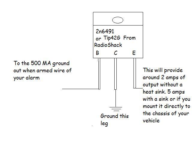
Since we too have left you on hold for over 4 hours, I have no idea about the current capacity of your sensor.  But I can tell you that this transistor is available for less than 2 dollars at your local Radio Shack store.  The left leg cannects to the output wire of your sensor.  The middle leg connects to ground.  The right leg connects to terminla 85 of your relay.  Apply power to terminal 86 of the relay.

506t glassbreak sensor -- posted image.

rgcme33 
Member - Posts: 23
Member spacespace
Joined: June 23, 2009
Location: South Carolina, United States
Posted: July 01, 2009 at 7:14 PM / IP Logged  

Thanks for responding! Are you seying this transistor will upgrade the output to ensure its sufficient? How will this help me.

And with regards to the diagram, it says connect to 200ma output, but I am not sure if the sensors output is even 100ma which it would need to be to drive the relay. But this diagram says it needs to be 200ma just to drive the transistor. A little confused, pls help ;)

i am an idiot 
Platinum - Posts: 13,667
Platinum spaceThis member consistently provides reliable informationspace
Joined: September 21, 2006
Location: Louisiana, United States
Posted: July 01, 2009 at 7:31 PM / IP Logged  
The diagram was drawn for an alarm that had a 500 Milliamp output.  The transistor needs virtually no current at all to trigger it.  Just connect it as I described.  It will do exactly what you need. 
rgcme33 
Member - Posts: 23
Member spacespace
Joined: June 23, 2009
Location: South Carolina, United States
Posted: July 01, 2009 at 8:16 PM / IP Logged  

i am an idiot wrote:
The diagram was drawn for an alarm that had a 500 Milliamp output.  The transistor needs virtually no current at all to trigger it.  Just connect it as I described.  It will do exactly what you need. 

Great, thanks a lot for the suggestion. Does it matter that the sensor ouput is negative?  I will already be using the relay to convert the polarity for my application, but I would need the transistor before the relay, so does this change anything about the instructions?  thanks again!

i am an idiot 
Platinum - Posts: 13,667
Platinum spaceThis member consistently provides reliable informationspace
Joined: September 21, 2006
Location: Louisiana, United States
Posted: July 01, 2009 at 8:47 PM / IP Logged  
That circuit is designed to take a low current negative wire and make it handle much more current.  A Bosch relay draws only 160 milliAmps of current.  This device will easily provide 2 amps of current capacity without having to mount it on a heat sink.

Sorry, you can NOT post a reply.
This topic is closed.

  Printable version Printable version Post ReplyPost New Topic
You cannot post new topics in this forum
You cannot reply to topics in this forum
You cannot delete your posts in this forum
You cannot edit your posts in this forum
You cannot create polls in this forum
You cannot vote in polls in this forum

  •  
Search the12volt.com
Follow the12volt.com Follow the12volt.com on Facebook
Friday, April 26, 2024 • Copyright © 1999-2024 the12volt.com, All Rights Reserved Privacy Policy & Use of Cookies
Disclaimer: *All information on this site ( the12volt.com ) is provided "as is" without any warranty of any kind, either expressed or implied, including but not limited to fitness for a particular use. Any user assumes the entire risk as to the accuracy and use of this information. Please verify all wire colors and diagrams before applying any information.

Secured by Sectigo
the12volt.com spacer
Support the12volt.com
Top
the12volt.com spacer