the12volt.com spacer
icon

door popper switch like tvr


Post ReplyPost New Topic
< Prev Topic Next Topic >
djsri 
Member - Posts: 3
Member spacespace
Joined: July 23, 2009
Location: United Kingdom
Posted: July 23, 2009 at 8:47 AM / IP Logged  

Hi All

i've just purchased a remote door popper kit/Shaved handles by (Autoloc) which works by using the remote keyfob to pop the doors. I'm going to install some switches under the mirriors and pop the doors this way (Like TVR setup) as M.O.T here in the UK need some form of manual entry. My question is, can i use my toad AI606 alarm to send power (Be + or -) to the buttoms on disarm and kill the power when armed?

I've been reading on this site about the latching setup but unsure how to setup switch to fire solenoid allcontrolled by the alarm.

Thanks for any info

howie ll 
Pot Metal - Posts: 16,466
Pot Metal spacespace
Joined: January 09, 2007
Location: United Kingdom
Posted: July 23, 2009 at 2:31 PM / IP Logged  
You can use a timed aux output, I think the toad has a white wire, time it to 20secs, and power a relay, programme it to work whether alarm is armed or disarmed.
djsri 
Member - Posts: 3
Member spacespace
Joined: July 23, 2009
Location: United Kingdom
Posted: July 23, 2009 at 4:44 PM / IP Logged  

Hi Howie

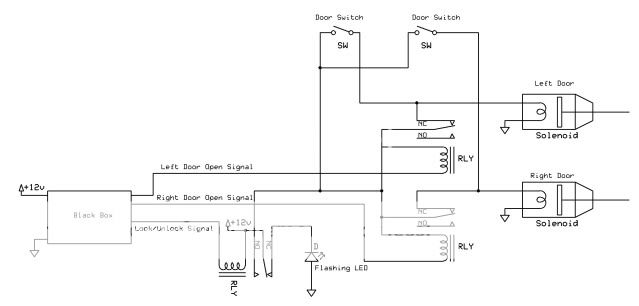
Many thanks for the reply i will check this wire out. Can you make sense of this wiring diagram? not sure what how this is wired. I.e pins 30,85,86 etc

door popper switch like tvr -- posted image.

howie ll 
Pot Metal - Posts: 16,466
Pot Metal spacespace
Joined: January 09, 2007
Location: United Kingdom
Posted: July 24, 2009 at 1:32 AM / IP Logged  
Take the white (?)  output from your Toad, set it for timed 30 secs, parallel wire to the wire marked "lock unlock signal" from the black box, I would install 2 x 1N4004 diodes inline before the join, bands away from the join, take to 85 on your relay, 12volts (fused) to 86 and 87 (shown as NO) then output from 30 to the LED (I assume that's provided, if not diodes and 12v+ flashing LED from Maplin). That's a lousy diagramme, it shows 30 and 87a both joined to 87 in fact if its a 4 pin relay, use 87 as in and 30 as out, if it's a 5 pin relay ignore 87a  With the second relays, 86 from the first, 87 from power source, 85 to ground (earth) and 30 is output.  Come to think of it the door switches are in the wrong position as well, I'd do that with 2 relays and eliminate some of that wiring. Don't ask me how, it's professwional knowledge, I'll give you a clue, you don't need the magic box or the first relay.
djsri 
Member - Posts: 3
Member spacespace
Joined: July 23, 2009
Location: United Kingdom
Posted: July 24, 2009 at 4:08 AM / IP Logged  

Howie

Thank you for taking the time to explain the wiring diagram to me. It was a diagram i found on the net and it sounded like the same thing i was trying to achive!

The only thing i'm trying to achive is, if i leave my keys in the car and shut the door (Shaved Handles, Wished i had not bothered now!) is to be able to still pop the doors from the switch under the mirror. Arm the alarm power has gone, can i work this out....hell no...

The white wire sound great but i dont think it will work, as if the car is at the MOT testing station they shut the door 5 mins later oppsss (unless hidden switch somewhere) not really keen on that.

Do you know anybody in Wilts area could come and view?

redhondapimp 
Member - Posts: 14
Member spacespace
Joined: November 02, 2004
Location: Kansas, United States
Posted: July 26, 2009 at 11:58 AM / IP Logged  

Just a idea...it could go either way...adding a switchfor the popper that has power all the time, but putting it in a very super duper sneaky, pain in the all place to get to as a back up?


Sorry, you can NOT post a reply.
This topic is closed.

  Printable version Printable version Post ReplyPost New Topic
You cannot post new topics in this forum
You cannot reply to topics in this forum
You cannot delete your posts in this forum
You cannot edit your posts in this forum
You cannot create polls in this forum
You cannot vote in polls in this forum

  •  
Search the12volt.com
Follow the12volt.com Follow the12volt.com on Facebook
Thursday, May 8, 2025 • Copyright © 1999-2025 the12volt.com, All Rights Reserved Privacy Policy & Use of Cookies
Disclaimer: *All information on this site ( the12volt.com ) is provided "as is" without any warranty of any kind, either expressed or implied, including but not limited to fitness for a particular use. Any user assumes the entire risk as to the accuracy and use of this information. Please verify all wire colors and diagrams before applying any information.

Secured by Sectigo
the12volt.com spacer
Support the12volt.com
Top
the12volt.com spacer