the12volt.com spacer
icon

door lock actuators with remote start


Post ReplyPost New Topic
< Prev Topic Next Topic >
jon720 
Member - Posts: 1
Member spacespace
Joined: October 28, 2009
Posted: October 28, 2009 at 11:13 PM / IP Logged  

Okay, so I've been trying to add keyless entry and remote start to my sisters' 2005 Honda CIvic, the car did not come with power locks so I had to add actuators to both doors.  I'm using a Bulldog RS1100 remote start which also happens to have outputs for door lock and unlock.  I have added Harada two wire actuators to both the drivers and passenger doors and am attempting to trigger them using the RS1100. 

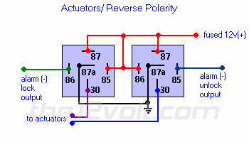
I've set up a system of relays as follows in this diagram:

door lock actuators with remote start -- posted image.

The RS1100 is setup for negative trigger lock and unlock and has a wire that is run to both relays for both lock and unlock respectively.  It also has a 12v+ wire on the door lock harness that I currently have connected to ground as per the Bulldog instructions.

The problem I am having is that the lock actuators are only moving in one direction...no matter if I press lock or unlock, the actuators only move in one direction.  The car will lock over and over, but not unlock.  The RS1100 only has one button and is supposed to automatically alternate between lock and unlock, but it appears to only be activating the lock signal. 

I've been wracking my brain for days trying to figure this out, it's like the polarity has to be reversed somehow...I doubt the remote start is faulty, I am sure it's just not wired right... 

I'm debating just ordering an aftermarket lock kit and boycotting the relay setup. 

Thoughts?

howie ll 
Pot Metal - Posts: 16,466
Pot Metal spacespace
Joined: January 09, 2007
Location: United Kingdom
Posted: October 29, 2009 at 1:43 AM / IP Logged  
Have you checked the lock/unlock outputs from the bulldog, made sure that they pulse neg in sequence?  Have you taken each (pair) of motor wires and attached one side to live then flashed the other side to ground to test each motor first? 
absolutepower 
Copper - Posts: 98
Copper spacespace
Joined: November 28, 2007
Location: California, United States
Posted: October 30, 2009 at 3:52 PM / IP Logged  
it sounds like the actuators are wired wrong. on the door actuators there should be two wires coming out from it thats the lock and unlock. lock wire should be on the 30 of one relay and the unlock should be on the 30 of the other relay as shown in the relay diagram u posted. the wires from the door actuators goes straight to the relays. 
howie ll 
Pot Metal - Posts: 16,466
Pot Metal spacespace
Joined: January 09, 2007
Location: United Kingdom
Posted: October 30, 2009 at 5:22 PM / IP Logged  
Why would the actuators be wired wrong if jon720 followed the diagramme in his post?
Mike M2 
Platinum - Posts: 2,652
Platinum spacespace
Joined: June 29, 2005
Location: United States
Posted: October 30, 2009 at 6:38 PM / IP Logged  
TRy this, remove the wires from 85/86 comming from the alarm. Take a piece of wire and try grounding each terminal one at a time. One term should lock and the other unlock. If they do the problem is on the alarm side, if they don't work right the problem is with your relay wiring....
Mike M2
Tech Manager
CS Dealer Services

Sorry, you can NOT post a reply.
This topic is closed.

  Printable version Printable version Post ReplyPost New Topic
You cannot post new topics in this forum
You cannot reply to topics in this forum
You cannot delete your posts in this forum
You cannot edit your posts in this forum
You cannot create polls in this forum
You cannot vote in polls in this forum

  •  
Search the12volt.com
Follow the12volt.com Follow the12volt.com on Facebook
Friday, March 29, 2024 • Copyright © 1999-2024 the12volt.com, All Rights Reserved Privacy Policy & Use of Cookies
Disclaimer: *All information on this site ( the12volt.com ) is provided "as is" without any warranty of any kind, either expressed or implied, including but not limited to fitness for a particular use. Any user assumes the entire risk as to the accuracy and use of this information. Please verify all wire colors and diagrams before applying any information.

Secured by Sectigo
the12volt.com spacer
Support the12volt.com
Top
the12volt.com spacer