Thanks Howie!
Alas Rookie hereon means up to 50 posts until I can post diagrams which I think is a bit excessive, but I didn't expect to be this active (this being my 28th post).
Though I can't help thinking of my poor colleague who is far from a Rookie yet seems to be considered anything but.
But unlike me, he hasn't learned to NOT reply to moron sites!! (EG - after pointing out a certain wiring error, the best the knockers could reply was "so why is everyone else doing it?". Their other arguments were nothing more than confirmations of what he wrote or worse.)
But in answer to your split charging system - Yes.
However I'll qualify that....
Cezar's system is merely two independent systems systems sharing a common ground.
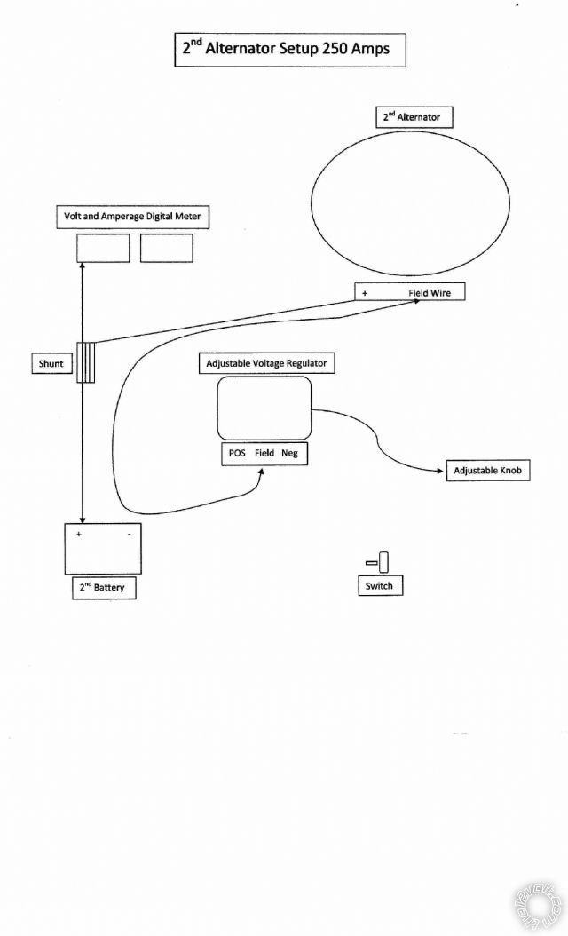
As I see it, he needs nothing more than to connect his 2nd battery via his fuse to the 2nd alternator and its load. (Noting that if only one 250A 2nd fuse, it is to protect the wiring from battery - the alternator should be self protecting and its wiring capable of withstanding at least 250A steady state - ie, rated at say 350A using a 70% loading rule).
Cezar merely needs an on-off switch to supply the 2nd battery's +12V to the 2nd alternator's external voltage regulator.
(And the 2nd alternator's voltage set as high as needed for desired output keeping in mind it should be sensing the 2nd battery's charging voltage where 14.4V is a normal "steady-state maximum" and 13.8V is the normal "float" voltage - depending on the battery, and how long you want it to last lifecycle-wise.)
It should also be possible to charge the 2nd battery off the primary alternator & battery circuit by using a common "charge lamp" circuit (off the primary alternator.... obviously....) PROVIDED the 2nd alternator is NOT charging the 2nd battery (because that would mean 2 alternators fighting each other).
IE - Cezar's "enable 2nd alternator" switch is powered from the head unit with a series manual "override" switch to power the 2nd regulator (probably via a relay to get full 2nd battery voltage to the 2nd regulator's sense input - presumably its +12V supply). The series override switch should be a changeover (SPDT) to interlock the "charge 2nd battery from primary alternator" - ie, so you can't charge (the 2nd battery hence everything off...) BOTH alternators.
As to "
decent quality split charging system"...
I happen to agree with my aforementioned colleague that the split charging systems we have seen are a crock of bullsh aka spousetales (to borrow his jargon).
I too have seen systems that describe "charging of the second battery ONCE the first has charged".
Without going into the alleged logic of this, we are yet to see a system that current limits and treats each battery individually.
We both run twin battery systems where the second battery is paralleled to the first whenever the engine is charging, else it is isolated. (We both STUPIDLY used an overvoltage sensor to do this until we realised a much simpler method that merely required a simple relay!)
I have yet to see any argument against our method (excluding current limiting when the 2nd battery is smaller or of AGM etc type, but few of the "split charging systems" provide that anyhow.... let alone traditional primary systems!)
Anyhow, the final wiring diagram is somewhat dependent on the 2nd regulator's (and its alternator's) layout, but it is very likely to look much simpler than all the guff above!
I hope!
Let me know if I have committed the same mistake as my abovementioned colleague - and I do NOT mean mean "posting to morons" (!!!), but instead mean "treading on sacred ground" etc...
(Alas my dear colleague has just left a prominent site due to unqualified/unotified "censorship" of his posts. Not that he thinks profits nor egos should be protected, but he has limited persistence - and he enjoys a really good laugh "after the fact".)
Again, thanks for the compliment. I hope I haven't just blown it! (Come 50 posts and I may remove any offending parts!)


 Printable version


