the12volt.com spacer
icon

delay relays


Post ReplyPost New Topic
< Prev Topic Next Topic >
icearrow6 
Copper - Posts: 497
Copper spacespace
Joined: February 02, 2009
Location: California, United States
Posted: December 20, 2009 at 3:00 AM / IP Logged  
Hiya Fellas:
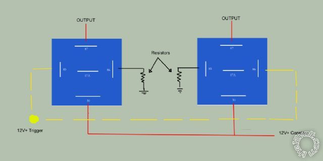
I want to set up a couple of relays that will allow me to delay the output of each relay by changing the ground resistor size.
I think i'll just trial and error to figure out the exact time i want between the outputs. Its for a sequential lighting project that i have in mind.
I just want the opinion of the relay experts here if my simple schematic here is correct.
delay relays -- posted image.
howie ll 
Pot Metal - Posts: 16,466
Pot Metal spacespace
Joined: January 09, 2007
Location: United Kingdom
Posted: December 20, 2009 at 6:52 AM / IP Logged  
Look at this item on relays on this site, you will find you need caps as well, and the resistor/cap combination varies the time delay.
i am an idiot 
Platinum - Posts: 13,709
Platinum spaceThis member consistently provides reliable informationspace
Joined: September 21, 2006
Location: Louisiana, United States
Posted: December 20, 2009 at 8:13 AM / IP Logged  

Howie has been paying attention and taking notes, hasn't he?    I still have not found the diagram that I know is on this site somewhere.  Depending on the amount of delay you want the capacitor and resistor will both affect the time.  Larger capacitor = more delay.  Higher value resistor will also increase the delay time.  47 ohm 2 watt resistor and a 4700 mic capactior may be a good starting point.  You can parallel capacitors to increase the value.  4700 + 2200 = 6900

https://www.the12volt.com/installbay/forum_posts.asp?tid=113479&KW=delay+relay&tpn=1#548122

icearrow6 
Copper - Posts: 497
Copper spacespace
Joined: February 02, 2009
Location: California, United States
Posted: December 20, 2009 at 11:47 AM / IP Logged  
Thx for the info.
Howiee the relay diagrams that i could find were only to provide a temporary pulse using the mention cap/resistor setup.
I did look around for about 30 mins, but couldn't find it, :/
So delay the trigger via cap / resistor. GOT IT!
Iam could you tell me why supplying constant 12v+ to the relay coil and adding resistance to the (-) won't delay the relay coil?
THX again guys.
howie ll 
Pot Metal - Posts: 16,466
Pot Metal spacespace
Joined: January 09, 2007
Location: United Kingdom
Posted: December 20, 2009 at 11:54 AM / IP Logged  
Your right they will only work for about 30secs. I found a UK manufacturer who made them to run computers, games etc. but I'm damned if I remember them! I think Google will have to be your friend!
i am an idiot 
Platinum - Posts: 13,709
Platinum spaceThis member consistently provides reliable informationspace
Joined: September 21, 2006
Location: Louisiana, United States
Posted: December 20, 2009 at 12:13 PM / IP Logged  
The resistor will only add resistance to the circuit.  It just won't delay it.  The delay comes in when the line has to charge the capacitor through the resistor.  The cap will not charge instantly.  That is the only simple way I know of to delay the turn on of a relay.
oldspark 
Gold - Posts: 4,913
Gold spacespace
Joined: November 03, 2008
Location: Australia
Posted: December 20, 2009 at 4:30 PM / IP Logged  
It depends on how long the delay is.
Because solenoids are a relatively high current, large capacitors may be required.
For long delays, a smaller RC combination feeding a transistor of FET (or a "smaller" relay) is usually used.
Alternatively delay circuits using counter or 555-time chips (IC) are common.

Sorry, you can NOT post a reply.
This topic is closed.

  Printable version Printable version Post ReplyPost New Topic
You cannot post new topics in this forum
You cannot reply to topics in this forum
You cannot delete your posts in this forum
You cannot edit your posts in this forum
You cannot create polls in this forum
You cannot vote in polls in this forum

  •  
Search the12volt.com
Follow the12volt.com Follow the12volt.com on Facebook
Thursday, May 15, 2025 • Copyright © 1999-2025 the12volt.com, All Rights Reserved Privacy Policy & Use of Cookies
Disclaimer: *All information on this site ( the12volt.com ) is provided "as is" without any warranty of any kind, either expressed or implied, including but not limited to fitness for a particular use. Any user assumes the entire risk as to the accuracy and use of this information. Please verify all wire colors and diagrams before applying any information.

Secured by Sectigo
the12volt.com spacer
Support the12volt.com
Top
the12volt.com spacer