the12volt.com spacer
icon

3rd brake light strobe?


Post ReplyPost New Topic
< Prev Topic Next Topic >
jayson33 
Copper - Posts: 165
Copper spacespace
Joined: June 12, 2008
Location: Indiana, United States
Posted: February 18, 2010 at 11:26 PM / IP Logged  

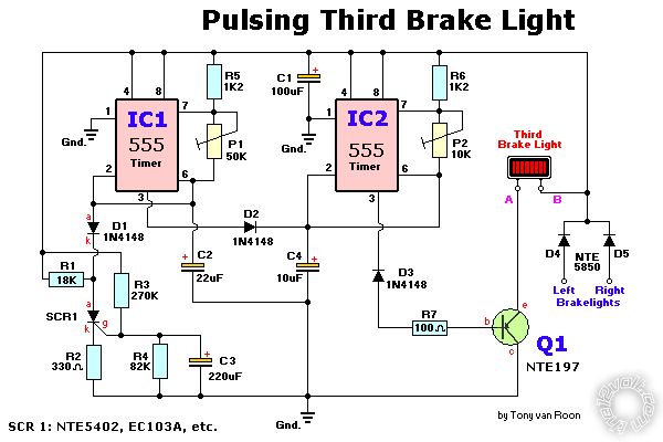
3rd brake light strobe? -- posted image.

Can anyone tell me If this looks like it will work?

My wife thinks bagging a truck means you kick it in the truck nuts
oldspark 
Gold - Posts: 4,913
Gold spacespace
Joined: November 03, 2008
Location: Australia
Posted: February 19, 2010 at 10:38 PM / IP Logged  
Why shouldn't it? It's been around for years including the LED upgrade.
A later diagram says it corrects the orientation of D3, but that doesn't make sense to me seeing as Q1 is PNP. Then again, a PNP doesn't make sense - shouldn't it be an NPN?
I suspect sentex.ca/~mec1995/circ/motflash to be a better circuit (read the Updates at the bottom). That's referred to from sentex.ca/~mec1995/circ/flashing in turn from sentex.ca/~mec1995/circ/circuits.
jayson33 
Copper - Posts: 165
Copper spacespace
Joined: June 12, 2008
Location: Indiana, United States
Posted: February 20, 2010 at 12:04 AM / IP Logged  
Your's looks alot simpler than the one I have. Thanks
My wife thinks bagging a truck means you kick it in the truck nuts
oldspark 
Gold - Posts: 4,913
Gold spacespace
Joined: November 03, 2008
Location: Australia
Posted: February 20, 2010 at 2:40 AM / IP Logged  
Your welcome.
Did you see that kits were available?
And the article says that it's better than the 555 version, and has no initial delay.
I love the 555, but I learned years ago never to use the dual 556 - it was better using 2 separate 555s. (I did the impossible - an electronic "Halda" - an accurate odometer for Rallying etc; its readout was units of 10 yards/meters. It needed pulse/frequency multiplication. I used one 555 to gate another so one pulse in became about 200 pulses out - similar to the brake flasher. PLLs (Phase Locked Loops) became available later, and now CPUs.)
Not that a 556 is used above, but it can typify dual 555 circuits.
And the 2nd circuit has only one chip (14-pin quad Schmidt NAND) instead of two 555s. The gates (NANDs) do not have the same problems a 555s - ie, high switching transients, different behavior depending on the manufacturer. And they're about the same price (a bit more than a 555, but cheaper than two 555s).
The other thing I like about the 2nd circuit is the revision history - it seems to work. (Note the person that used a battery charger to power it, hence it wouldn't work. That's one for 12volt audiophiles.)
The original twin-555 circuit is a bit vague... (D3 direction, PNP vs NPN etc).
Good luck!

Sorry, you can NOT post a reply.
This topic is closed.

  Printable version Printable version Post ReplyPost New Topic
You cannot post new topics in this forum
You cannot reply to topics in this forum
You cannot delete your posts in this forum
You cannot edit your posts in this forum
You cannot create polls in this forum
You cannot vote in polls in this forum

  •  
Search the12volt.com
Follow the12volt.com Follow the12volt.com on Facebook
Tuesday, April 16, 2024 • Copyright © 1999-2024 the12volt.com, All Rights Reserved Privacy Policy & Use of Cookies
Disclaimer: *All information on this site ( the12volt.com ) is provided "as is" without any warranty of any kind, either expressed or implied, including but not limited to fitness for a particular use. Any user assumes the entire risk as to the accuracy and use of this information. Please verify all wire colors and diagrams before applying any information.

Secured by Sectigo
the12volt.com spacer
Support the12volt.com
Top
the12volt.com spacer