the12volt.com spacer
icon

pulsing input to relay to constant output


Post ReplyPost New Topic
< Prev Topic Next Topic >
dereileak 
Copper - Posts: 113
Copper spacespace
Joined: January 29, 2010
Location: Minnesota, United States
Posted: March 03, 2010 at 12:25 AM / IP Logged  
Ok, for my peizo siren I have it hooked up to the horn honk output on my alarm, its the only way please dont tell me to wire it differently, all I want is to take that pulsing 12 volt signal when the alarm is off, and get it to stay constant until the honk pulsing is done. It activates a peizo siren in the car, but has to pulse, the reason I have to hook up to that is because I have a proximity sensor that would chirp the peizo siren if hooked up different, so I had to go to the horn honk output so that it would not go off inside when the warning chirp would go off, causing my audio sensor to go off, so any ideas?
Viper 5902 - Ordered
Kicker Dual CVX 15's - Installed
Kicker ZX 1500.1 Amp - Installed
i am an idiot 
Platinum - Posts: 13,667
Platinum spaceThis member consistently provides reliable informationspace
Joined: September 21, 2006
Location: Louisiana, United States
Posted: March 03, 2010 at 6:54 AM / IP Logged  

The following is designed to work with a positive pulse.  If you need a ground pulse, I have a diagram for that.  The parts are the same, just set up a bit different.  Let me know if you need the other one.

Pulsed to Steady Output ( link)
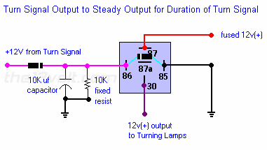
If you have cornering lights and want them to come on only when your turn signal is on and you do not have a steady output, use the following for each side. This will give you a steady output while the turn signal is on. Increasing the size of the capacitor will give you a longer output if needed.
 
pulsing input to relay to constant output -- posted image.

dereileak 
Copper - Posts: 113
Copper spacespace
Joined: January 29, 2010
Location: Minnesota, United States
Posted: March 03, 2010 at 2:29 PM / IP Logged  
yea, the horn wire is a ground output, I think either 200ma or 500ma, then it will trigger some kinda setup to set of the horn inside constant until the horn negative trigger stops, which will then stop the inside peize horn, thanks for the help, I think it will need a negative setup though
Viper 5902 - Ordered
Kicker Dual CVX 15's - Installed
Kicker ZX 1500.1 Amp - Installed
dereileak 
Copper - Posts: 113
Copper spacespace
Joined: January 29, 2010
Location: Minnesota, United States
Posted: March 04, 2010 at 9:56 PM / IP Logged  
hello?
Viper 5902 - Ordered
Kicker Dual CVX 15's - Installed
Kicker ZX 1500.1 Amp - Installed
i am an idiot 
Platinum - Posts: 13,667
Platinum spaceThis member consistently provides reliable informationspace
Joined: September 21, 2006
Location: Louisiana, United States
Posted: March 04, 2010 at 10:53 PM / IP Logged  
Sorry, I forgot.  The modified pic is on another computer.  i hope I remember to look for it in the morning.
i am an idiot 
Platinum - Posts: 13,667
Platinum spaceThis member consistently provides reliable informationspace
Joined: September 21, 2006
Location: Louisiana, United States
Posted: March 04, 2010 at 11:06 PM / IP Logged  

A 500MA output will not charge a 10,000 mic capacitor.  You wil have to use 2 relays.  Wire the first relay as follows.  500ma output to 85, constant to 86.  Ground to 30, connect the diode to terminal 87.  The diode need s to be turned around.   Banded end towards first relay.  Non banded end connects to the capacitor , the resistor and 86 of the second relay.  Other end of the cap and resistor are to be connected to power.  Unlike in the picture.  85 of the second relay connects to power.

If you need positive output connect power to 30 of second relay, and 87 of second relay is positive output.

If you need ground out, connect ground to 30 of second relay and 87 of second relay is ground out.

The picture I thought I had was a constant to momentary. 

dereileak 
Copper - Posts: 113
Copper spacespace
Joined: January 29, 2010
Location: Minnesota, United States
Posted: April 06, 2010 at 10:22 PM / IP Logged  
Ok, so I am gonna put diagrams on how to do this, it goes as follows
So you would have the negative horn honk output go into this relay diagram here:
pulsing input to relay to constant output -- posted image.
And then the positive of that one would go into this diagram here
pulsing input to relay to constant output -- posted image.
And this will convert a negative pulsing signal to a constant Positive signal that can power a siren or what ever you want!!
That way the inside peizo siren will ONLY sound when the car goes into full alarm, it will not sound for car finder, or warn away or anything that does not trigger the full alarm, that way you dont hurt anyones ears that are sitting inside the car, unless there trying to steal your stuff of course!
Sweetness
~Dereileak~
Viper 5902 - Ordered
Kicker Dual CVX 15's - Installed
Kicker ZX 1500.1 Amp - Installed
irocelcoss 
Member - Posts: 13
Member spacespace
Joined: March 31, 2010
Location: United States
Posted: April 07, 2010 at 6:22 PM / IP Logged  

Is the diagram you posted above correct ?  Looks like "I am an idiot"  said to ground 30.  We need a correct pic of exactly how do do each.....would make it easier to understand.

Also, in the pic there is a diode across 85 and 86 on the lower relay?  Clarification anyone?

Thanks

ace_boy2099 
Copper - Posts: 81
Copper spacespace
Joined: January 13, 2010
Location: Florida, United States
Posted: February 16, 2011 at 2:02 PM / IP Logged  

Relay Page wrote:
pulsing input to relay to constant output -- posted image. 

For this setup, the 10K uf capacitor and the 10K resistor What would the radioshack numbers for these be, Also, just for the sake of asking these wouldn't have to go to any circuit boards right, They're all inlines?? 

For the Resistors would these work?

that diod on the relay, How would that get wired? Could I just put it inline on 86 or 85?

Sorry so many questions, I've used relays before but never diods, resistors, and such. Thanks in advance.

ace_boy2099 
Copper - Posts: 81
Copper spacespace
Joined: January 13, 2010
Location: Florida, United States
Posted: February 26, 2011 at 11:01 PM / IP Logged  
no one viewing this???? Anyone with any info that could help me with this?????
Page of 2

  Printable version Printable version Post ReplyPost New Topic
You cannot post new topics in this forum
You cannot reply to topics in this forum
You cannot delete your posts in this forum
You cannot edit your posts in this forum
You cannot create polls in this forum
You cannot vote in polls in this forum

  •  
Search the12volt.com
Follow the12volt.com Follow the12volt.com on Facebook
Friday, April 19, 2024 • Copyright © 1999-2024 the12volt.com, All Rights Reserved Privacy Policy & Use of Cookies
Disclaimer: *All information on this site ( the12volt.com ) is provided "as is" without any warranty of any kind, either expressed or implied, including but not limited to fitness for a particular use. Any user assumes the entire risk as to the accuracy and use of this information. Please verify all wire colors and diagrams before applying any information.

Secured by Sectigo
the12volt.com spacer
Support the12volt.com
Top
the12volt.com spacer