the12volt.com spacer
icon

switch panel


Post ReplyPost New Topic
< Prev Topic Next Topic >
sabrev45 
Member - Posts: 3
Member spacespace
Joined: March 12, 2010
Location: Wisconsin, United States
Posted: March 12, 2010 at 10:05 AM / IP Logged  
I'm working on building a simple switch panel that consists of only two momentary switches. What I'm looking to do is wire it up so that when I hit one button, puts the current through the regular way, + to + and - to -. But I'm want to wire it up so that when I hit the other button, the two switch, so that the + is now running to the originally - side and the - is now running to the originally + side. How would I accomplish this?
Edit: this switch panel is going to be running a 12v electric motor. So I want it so that you hit one button and the motor runs normally and you hit the other and it switches polarity and runs in reverse.
Thanks,
Mike
KPierson 
Platinum - Posts: 3,527
Platinum spaceThis member consistently provides reliable informationspace
Joined: April 14, 2005
Location: Ohio, United States
Posted: March 12, 2010 at 12:38 PM / IP Logged  

It would be easier to use a DPDT three position switch (on off on).

What kind of contacts are on the switch you are using?  You'll most likely have to use the switches to latch a relay that does the power switching then have the other switch break the latch and latch a relay wired the opposite way.

Kevin Pierson
awdeclipse 
Copper - Posts: 285
Copper spacespace
Joined: August 05, 2007
Location: Michigan, United States
Posted: March 12, 2010 at 2:07 PM / IP Logged  
You could also use the DPDT switch to select direction and have a push button to run the motor as another option.
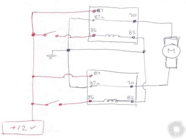
If you must have only two buttons you can do the following. You'll need 2 relays and two momentary push buttons. Don't forget fuses too! (I didn't include them in the diagram)
switch panel -- posted image.
Same as this diagram on the site already.
shafferny 
Copper - Posts: 240
Copper spacespace
Joined: February 02, 2008
Location: New York, United States
Posted: March 13, 2010 at 7:30 AM / IP Logged  

If found this diagram on the internet. It's simple enough. Your two center pins are your ouputs, and your top and bottom pins are your inputs. By changing the polarity of the inputs from top to bottom, you change the polarity output depending on which position the switch is in.

switch panel -- posted image.

anonymous1 
Copper - Posts: 151
Copper spacespace
Joined: October 25, 2009
Location: Washington, United States
Posted: March 14, 2010 at 12:19 PM / IP Logged  
Forgive me if I'm a tad under caffeinated today . . .
It sounds to me like he wants a 3 position momentary rocker switch.
In the middle position it does nothing.
In the UP position it would engage relay 1 for forward
In the down position it would engage relay 2 for reverse
Both positions are spring loaded momentary which require applied pressure for the duration of the action
When he let's go of pressing the UP or DOWN, the action would stop at that point.
OP is this for a winch? Do you plan to make this a type of external hand-held remote?
shafferny 
Copper - Posts: 240
Copper spacespace
Joined: February 02, 2008
Location: New York, United States
Posted: March 14, 2010 at 1:50 PM / IP Logged  

That was my understanding too.

It could be for a winch, power windows, whatever...I've been thinking about doing something similar in my Jeep Liberty to allow the rear passengers to change the radio station and volume.  

sabrev45 
Member - Posts: 3
Member spacespace
Joined: March 12, 2010
Location: Wisconsin, United States
Posted: March 15, 2010 at 11:02 AM / IP Logged  
shafferny wrote:

If found this diagram on the internet. It's simple enough. Your two center pins are your ouputs, and your top and bottom pins are your inputs. By changing the polarity of the inputs from top to bottom, you change the polarity output depending on which position the switch is in.

switch panel -- posted image.

If I was to use a relay setup like that, will I only need to use one relay? How would you go about wiring it up?
A three way momentary rocker switch sounds like a better option right now, I'll probably go with that instead.
awdeclipse 
Copper - Posts: 285
Copper spacespace
Joined: August 05, 2007
Location: Michigan, United States
Posted: March 15, 2010 at 11:21 AM / IP Logged  
Two relays are required for that setup.
Follow this link
The actuator wires would connect to your motor and then the momentary switches would connect to ground on one side and "alarm lock output" on the diagram, one switch for each side.
sabrev45 
Member - Posts: 3
Member spacespace
Joined: March 12, 2010
Location: Wisconsin, United States
Posted: March 15, 2010 at 11:26 AM / IP Logged  
awdeclipse wrote:
Two relays are required for that setup.
Follow this link
The actuator wires would connect to your motor and then the momentary switches would connect to ground on one side and "alarm lock output" on the diagram, one switch for each side.
Great, thanks for the help. That seems to be exactly what I need.
anonymous1 
Copper - Posts: 151
Copper spacespace
Joined: October 25, 2009
Location: Washington, United States
Posted: March 15, 2010 at 8:09 PM / IP Logged  

And all the people said "yea" . .  and there was much rejoicing

:D

Page of 2

  Printable version Printable version Post ReplyPost New Topic
You cannot post new topics in this forum
You cannot reply to topics in this forum
You cannot delete your posts in this forum
You cannot edit your posts in this forum
You cannot create polls in this forum
You cannot vote in polls in this forum

  •  
Search the12volt.com
Follow the12volt.com Follow the12volt.com on Facebook
Monday, May 6, 2024 • Copyright © 1999-2024 the12volt.com, All Rights Reserved Privacy Policy & Use of Cookies
Disclaimer: *All information on this site ( the12volt.com ) is provided "as is" without any warranty of any kind, either expressed or implied, including but not limited to fitness for a particular use. Any user assumes the entire risk as to the accuracy and use of this information. Please verify all wire colors and diagrams before applying any information.

Secured by Sectigo
the12volt.com spacer
Support the12volt.com
Top
the12volt.com spacer