alright, while a rookie,, I have done this mod myself so I speak from under the shade tree. firstly the fan you are using is one of the most popular fan mods around. many a ford in junk yards are fan less as we speak because it is known as one of the best pulling fans around. brand new these fans will draw around 40 to 50 amps on hi speed start up. with age and use the resistance of the fan builds and start up amperage increases until either the fan goes bad or you melt something, translation: if its drawing 100amps, its time to find a new one. now the high amp draw should only last for a moment as once the fan starts rotating the current draw drops quickly to it's normal draw, some where around 30 or so amps, if it continues to draw extremely high amps(your fuse will blow) it's time to find a new fan. I have charts and actual data bookmarked somewhere if you want it.
now lets get to it, you will need four high amp relays(radio shack, ebay,internet) I just found an 80amp relay on Amazon for $10(60 will do), which is more than you should need. an inline fuse holder and fuse, 50amp slow blow type, I would use a maxi type. four 15amp inline fuses, enough #10 wire for your installation, enough #16 wire for your installation. a temperature sending unit, the probe type is the easiest to install, get one that you can adjust and set it to about 20 degrees over your normal operating temperature (you can find them all over the net, get a decent one)wire ties, squeeze taps, and all the little odds and ends most wrench heads have lying around. I would recommend soldering connections and using ring terminals where appropriate. also make sure to secure your lines, and tape or shrink tube your connections. now on to the install.
Make sure that no wires are left hanging freely where they might get pulled on or come into contact with moving parts, also I like to wire tie wires to the car harness where I can as they usually pick the safest route. make sure your wire are well clear of hot engine parts so that they do not contact and melt causing a dead short.
Firstly, you wanted your fan to come on with your key, I don't recommend this and will not tell you how to do it. believe it or not you can over cool a car. they are designed to operate at a certain temperature and should not be allowed not to. believe me I'm saving you a lot of headaches and a lot of gas. if your having overheating problems, this will not help, your problem is elsewhere. I can also assume it's not a race car as you would only need high speed. so what I'm describing will cause your fan to cycle on low when your car tells it too and Hi when your ac clutch is engaged or your vehicle gets a little to hot(i.e. sitting in heavy traffic, really over revving, or you live in hell!).
disconnect the negative wire on your battery. you will need to find a ignition on power source, this can be found in your fuse box, try the radio fuse, tap off this line with a # 16 wire long enough to reach the location you plan on mounting your bank of relays, run it backwards from the bank to your fuse box, its easier that way, run it through a firewall grommet,secure it with wire ties along the way. fuse it with a 15amp inline fuse within 12 inches of the fuse box. next install and ground your fan to an appropriate ground with #10 wire to a chassis ground. next using a ring terminal of the appropriate size, connect #10 wire to the positive side of your battery, put your 50amp inline fuse within 18 inches of the battery. and run the line to where your relay bank will be located. locate the positive line to your ac clutch. tap into to this line with # 16 wire, I would use a squeeze tap, fuse this line with a 15 amp inline fuse within 6 inches of the tap, run the line back to your relay bank, secure it along the way with wire ties. install you temperature sending unit and run the wire back to your relay bank, follow the manufactures directions, wire tie the wires along the way.connect a #10 wire to the low side of your fan and run it back to your relay bank, connect another #10 wire to the hi side of your fan and run that back to your relay bank, secure the wires with wire ties.find your original fan control wire, try to find the control wire that controls the fan relay, not the high power line from the relay to the fan, to much amperage and just more headaches, tap into this line with a squeeze tap, install a 15amp inline fuse within 6 inches of your tap, run the wire back to your relay bank, wire tie where appropriate.
now this is your install, so where you've located your relay bank is up to you, a nice clean spot on the fender wall will do nicely.
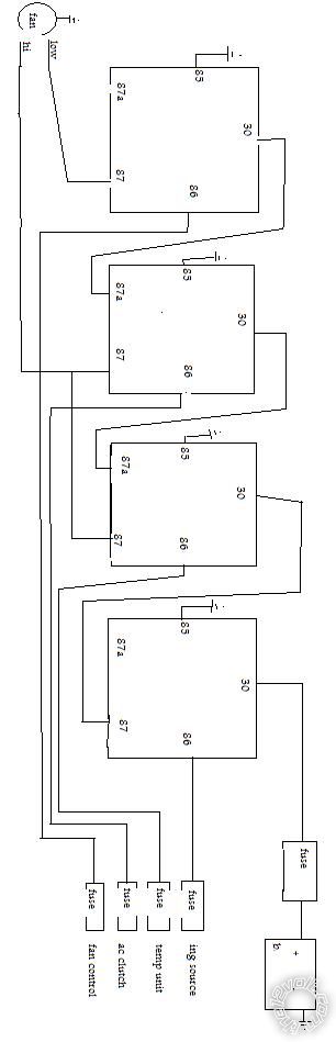
to wire your first relay, connect your #10 positive battery line to the #30 terminal of the relay, connect the fused ignition line to the # 86 terminal of the relay, connect terminal 85 to a chassis ground, connect a length of #10 wire long enough to reach the next relay to terminal #87.
to wire the second relay, connect the #10 wire from relay #1 to #30 terminal of the relay, connect a length of #10 wire long enough to reach teminal #30 on the next relay to terminal #87a, connect a length of # 10 wire long enough to reach terminal #87 of relay #3. now due to the fact I don't know what type of temperature probe your using, this part is on you, read your instructions to figure out your wiring, what you will need is positive on terminal 86 of the relay and negative on terminal 85 of the relay, wire appropriately.
to wire the third relay,connect the #10 wire from relay #2 (terminal #87a) to terminal #30, connect your ac clutch line to terminal #86, connect terminal #85 to chassis ground, connect the #10 wire form relay #2 terminal #87 and the hi fan wire to terminal #87, connect a #10 wire long enough to reach relay #4 to terminal #87a.
to wire your forth relay, connect the #10 wire from relay #3 to terminal #30, connect the original fan wire to to terminal #86, connect terminal #85 to ground, connect the low fan wire to terminal #87.
reconnect the negative battery cable. remember that your fan can kick on any time you have your key turned on.
well that's it, test your new fan system, I assumed you have some knowledge of cars in all of this, check it once, check it twice, I assume no responsibility. If there's anything else you need, or have any questions, please ask, good luck, Scott


 Printable version


