the12volt.com spacer
icon

stand alone starter interrupt relay fail


Post ReplyPost New Topic
< Prev Topic Next Topic >
rollinsmoke 
Member - Posts: 13
Member spacespace
Joined: January 18, 2010
Location: West Virginia, United States
Posted: April 23, 2010 at 3:46 PM / IP Logged  

I've used all kinds of your relay and other diagrams on here and I thank you ALL who take the time to put them up for people like me.

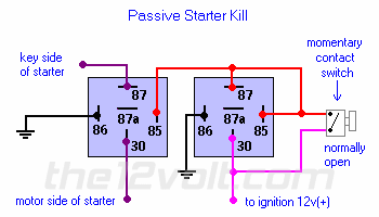
I have a PROBLEM,  Stand Alone starter kill, wired per the drawings and triple checked for correct pinout. This on a 205 Ford F 450.  If I try to start the truck normally it won't let me, (of course), I turn the ignition on and depress/release the momentary switch and it still won't start.  I have to keep the momentary switch depressed in order for it to start. Here's what I did:

Relay 1:

30  Engine side of starter wire

87  Ignition side of starter wire

86 Ground

85 Positive from momentary switch when depressed (NO)

Relay 2:

30  Ignition only power

85  Positive from momentary switch when depressed (NO)

87 Positive from momentary switch when depressed (NO)

86 Ground

          I'm sure I'm missing something obvious but,........??

THANKS

Still Learning
t&t tech 
Platinum - Posts: 2,608
Platinum spacespace
Joined: October 05, 2008
Location: Trinidad and Tobago
Posted: April 23, 2010 at 5:57 PM / IP Logged  
This is a stand alone starter kill. It does not rely on an alarm or keyless entry for it to work, only a simple momentary contact switch (normally open) to deactivate it. Every time the ignition is turned off, continuity is broken on the starter feed wire. To disable (or start), turn ignition on, then press the hidden switch, then start as normal.
 
stand alone starter interrupt relay fail -- posted image.
commit your way to jehovah and he will act in your behalf. psalms 37:5
t&t tech 
Platinum - Posts: 2,608
Platinum spacespace
Joined: October 05, 2008
Location: Trinidad and Tobago
Posted: April 23, 2010 at 6:00 PM / IP Logged  
You have it listed correctly, it's the actual wiring we can't account for!
commit your way to jehovah and he will act in your behalf. psalms 37:5
KPierson 
Platinum - Posts: 3,527
Platinum spaceThis member consistently provides reliable informationspace
Joined: April 14, 2005
Location: Ohio, United States
Posted: April 23, 2010 at 6:32 PM / IP Logged  

Check to make sure you have pin 87 connected to pin 85 of relay 2.

It sounds like the relay is not latching when you push the button with the ignition on.  The latch is formed between 87 and 85.

Also make sure that you have a true ignition source and not an accessory source that is dropping out when you crank.

Kevin Pierson
rollinsmoke 
Member - Posts: 13
Member spacespace
Joined: January 18, 2010
Location: West Virginia, United States
Posted: April 23, 2010 at 9:55 PM / IP Logged  
KPierson wrote:

Check to make sure you have pin 87 connected to pin 85 of relay 2.

It sounds like the relay is not latching when you push the button with the ignition on.  The latch is formed between 87 and 85.

Also make sure that you have a true ignition source and not an accessory source that is dropping out when you crank.

 The 87.85 o #2 is good.  I'll double check the "true ignition".

Thanks

Still Learning
dualsport 
Silver - Posts: 983
Silver spacespace
Joined: September 27, 2005
Location: United States
Posted: April 24, 2010 at 6:41 AM / IP Logged  
Sounds like you have the input connected to the start signal rather than the ignition switch line. Just find a line where the voltage comes up when you switch on the ignition and remains on throughout the start cycle.

Sorry, you can NOT post a reply.
This topic is closed.

  Printable version Printable version Post ReplyPost New Topic
You cannot post new topics in this forum
You cannot reply to topics in this forum
You cannot delete your posts in this forum
You cannot edit your posts in this forum
You cannot create polls in this forum
You cannot vote in polls in this forum

  •  
Search the12volt.com
Follow the12volt.com Follow the12volt.com on Facebook
Sunday, April 28, 2024 • Copyright © 1999-2024 the12volt.com, All Rights Reserved Privacy Policy & Use of Cookies
Disclaimer: *All information on this site ( the12volt.com ) is provided "as is" without any warranty of any kind, either expressed or implied, including but not limited to fitness for a particular use. Any user assumes the entire risk as to the accuracy and use of this information. Please verify all wire colors and diagrams before applying any information.

Secured by Sectigo
the12volt.com spacer
Support the12volt.com
Top
the12volt.com spacer