the12volt.com spacer
icon

2008 corolla, viper 5301


Post ReplyPost New Topic
< Prev Topic Next Topic >
davidcma 
Member - Posts: 11
Member spacespace
Joined: May 08, 2010
Posted: May 12, 2010 at 4:39 PM / IP Logged  
I’m planning to install viper 5301 on my 2008 corolla. Could somebody help me with heavy gauge 8-pin connector?
I went through many similar posts asking for the same question, but unfortunately, after they got it fixed no one bothered to leave a feedback as to how to connect those wires. I even PMed some of them, but no luck.
I know this was meant for professionals to install, but believe me, in this part of world it is very difficult to find one.
So here it goes.
H3/1     PINK          IGNITION 1 INPUT/OUTPUT
H3/2     RED / WHITE     (+) FUSED (30A) IGNITION 2 / FLEX RELAY INPUT 87
H3/3     ORANGE          ACCESSORY OUTPUT
H3/4     VIOLET          STARTER OUTPUT
H3/5     RED          (+) FUSED (30A) IGNITION 1 INPUT
H3/6     PINK/WHITE     (+) IGNITION 2 / FLEX RELAY OUTPUT 30
H3/7     PINK/BLACK     FLEX RELAY INPUT 87A key side (if required) of FLEX RELAY
H3/8     RED / BLACK     (+) FUSED (30A) ACCESSORY/STARTER INPUT
i understand that H3/2, H3/6 & H3/7 are part of onboard "Flex Relay", but no clue how to connect them.
My car has ignition 1, ignition 2, accessory, starter wires.
Many thanks in advance.
P.S. Here in summer temperature goes up to 50C (122F): cars are like saunas (furnaces).
I'll bless/thank you everytime i get in my cool corolla:)
shafferny 
Copper - Posts: 240
Copper spacespace
Joined: February 02, 2008
Location: New York, United States
Posted: May 12, 2010 at 5:01 PM / IP Logged  

I originally posted this here... https://www.the12volt.com/installbay/forum_posts.asp~TID~119777~KW~viper+5101~PN~0~TPN~3

See if this helps you out at all...

H3/1

PINK

IGNITION 1 INPUT/OUTPUT

This wire gets connected to the wire in the ignition harness that shows 12volts in both the "start" and "run" position.

H3/2

RED / WHITE

(+) FUSED (30A) FUSED IGNITION 2 /FLEX RELAY INPUT 87

This is the "input" for the flex relay. If needed, you will supply this wire with 12 volts constant.

Basically the flex relay is just a relay that can be programed to function, or "behave" if you will, in one of three ways. It can be programmed to be used as a second starter wire, a second accessory wire, or a second ignition wire. For example, if you're vehicle has two accessory wires that are normally powered up when your vehicle is running, then you'll need program the remote start module to make the flex relay behave as an accessory. By default it's programmed as a second ignition wire.

This wire has other uses if you want to get creative.

H3/3

ORANGE

ACCESSORY OUTPUT

This wire gets connected to the wire in the ignition harness that shows 12volts in the accessory and run positions.

H3/4

VIOLET

STARTER OUTPUT

This wire gets connected to the starter wire in the ignition harness. The starter wire shows 12volts in the start position only.

H3/5

RED

(+) FUSED (30A) IGNITION 1 INPUT

This wire gets connected to 12volts constant. It supplies power for  the H3/1 (PINK) wire when the vehicle is running via remote start.

H3/6

PINK/WHITE

IGNITION 2 / FLEX RELAY OUTPUT 30

This wire gets connected to your second ignition, second accessory, or second starter wire in the igntion harness, whichever you're going to program it for.  

H3/7

PINK/BLACK

FLEX RELAY INPUT 87A key side (if required) of FLEX RELAY

This wire is used when you need to isolate the ignition switch during the remote start operation.

As i understand it, when you start your vehicle with the key, power flows from the ignition switch through the H3/7(Pink/Black) and out the H3/6(Pink/White). Since the flex relay is at rest, contact 87a transfers power to contact 30 of the flex relay. When the vehicle is started with the remote starter then power from the H3/2(RED / White) puts power through to the H3/6(Pink/White).

H3/8

RED / BLACK

(+) FUSED (30A) ACCESSORY/STARTER INPUT

This wire should be connected to 12volts constant to power. It supplies the power for the H3/3(Accessory) and H3/4(Starter Output) wires.

davidcma 
Member - Posts: 11
Member spacespace
Joined: May 08, 2010
Posted: May 12, 2010 at 5:44 PM / IP Logged  
Thanks for the post. Now its 2:40 am with me, my eyes are closing. One comment though: i didn't absorb the words "if needed", "When you need". Do i need to isolate the ignition switch? Do i need to connect H3/2 with +12v constant?
Again, thanks for helping.
t&t tech 
Platinum - Posts: 2,608
Platinum spacespace
Joined: October 05, 2008
Location: Trinidad and Tobago
Posted: May 12, 2010 at 5:58 PM / IP Logged  
Eliminate the pink/black from the equation, power up all reds, and use the pink/white for the second ignition!
commit your way to jehovah and he will act in your behalf. psalms 37:5
davidcma 
Member - Posts: 11
Member spacespace
Joined: May 08, 2010
Posted: May 12, 2010 at 11:46 PM / IP Logged  
@t&t tech: Thanks for helping. I saw lots of posts of yours helping others. So i don't need to isolate the ignition switch, i.e. cut any of OEM wires?
Thanks in advance!
t&t tech 
Platinum - Posts: 2,608
Platinum spacespace
Joined: October 05, 2008
Location: Trinidad and Tobago
Posted: May 13, 2010 at 6:11 AM / IP Logged  
Nope, no need to cut anything! Unless you want an immobiliser circuit! I think the 5301 is just convenience anyway! Cheers mate, good luck on your endeavours!
commit your way to jehovah and he will act in your behalf. psalms 37:5
davidcma 
Member - Posts: 11
Member spacespace
Joined: May 08, 2010
Posted: May 13, 2010 at 3:24 PM / IP Logged  
Thanks man.
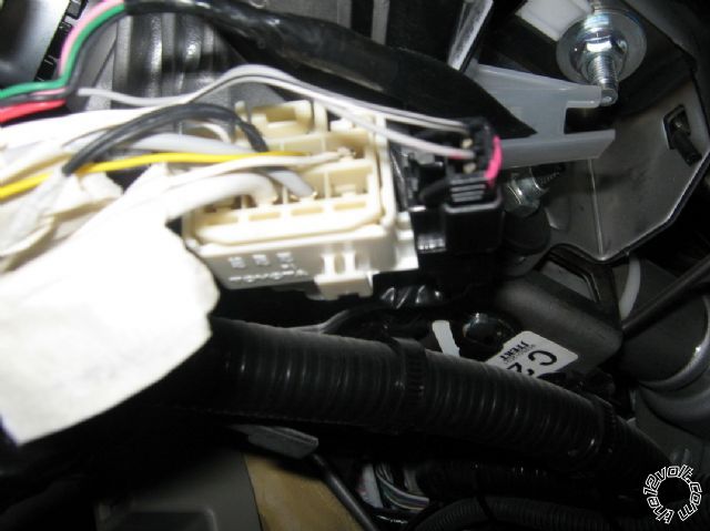
Today i actually looked at wires in my car. All of the wiring diagrams i was able to get were wrong. Ignition switch harness has got the following wires (from left to right in picture)
Upper row
1. Ignition 2 wire
2. Accessory - black
3. +12v const - yellow thin wire
4. Starter 2 - thin wire
Lower row
5. Starter - Heavy Gauge white wire
6. +12v const - heavy gauge white wire
7. Ignition wire - gray
How do i connect the wires in this scenario? And BTW, could you explain me, if Starter output wire gives +12v only on cranking time, why can't i connect the Starter & starter 2 wires to Brains single Starter output wire? And similarly ignition and ignition 2 wires to brains ignition 1 output wire?
2008 corolla, viper 5301 -- posted image.
kreg357 
Platinum - Posts: 7,783
Platinum spaceThis member has made a donation to the12volt.com. Click here for more info.spaceThis member has been recognized as an authority in Electrical Theory. Click here for more info.spaceThis member has been recognized as an authority in Mobile Security and Convenience. Click here for more info.spacespace
Joined: January 30, 2009
Location: Pennsylvania, United States
Posted: May 13, 2010 at 5:30 PM / IP Logged  

It looks like you have a 2009 Toyota Corolla made in Japan.  Check the wire listing from Bulldog  Security at :  http://www.bulldogsecurity.com/bdnew/vehiclewiringdiagrams.asp

As far as connecting a single R/S output wire to multiple wires in the cars ignition harness - Don't do it.  Just assume the manufacturer seperated and isolated those wires for a good reason.  

Soldering is fun!
davidcma 
Member - Posts: 11
Member spacespace
Joined: May 08, 2010
Posted: May 14, 2010 at 1:41 AM / IP Logged  
But i see no other choice, than to connect single Starter R/S output to Starter & Starter 2 wires in car, since i have two ignition & two starter wires. Even if i could reprogram H3/6 to output starter 2, what should i do with ignition 2 wire?
kreg357 
Platinum - Posts: 7,783
Platinum spaceThis member has made a donation to the12volt.com. Click here for more info.spaceThis member has been recognized as an authority in Electrical Theory. Click here for more info.spaceThis member has been recognized as an authority in Mobile Security and Convenience. Click here for more info.spacespace
Joined: January 30, 2009
Location: Pennsylvania, United States
Posted: May 14, 2010 at 5:17 AM / IP Logged  
Use the Vipers two IGN outputs for the cars two ignition wires.  Buy two +12v SPDT 30/40 Amp relays and two in-line fuse holders & 20 Amp fuses.  Then follow the diagram on page 20 of this Directed install guide ( the install guide is specifically for their Ready Remote R/S Model 24923, but has good basic info ).   http://www.designtech-intl.com/pdf/manuals/24923.pdf  The relays will make two Starter outputs from the Vipers single Start output (H3/4  Violet   Starter Output).
Soldering is fun!
Page of 3

  Printable version Printable version Post ReplyPost New Topic
You cannot post new topics in this forum
You cannot reply to topics in this forum
You cannot delete your posts in this forum
You cannot edit your posts in this forum
You cannot create polls in this forum
You cannot vote in polls in this forum

  •  
Search the12volt.com
Follow the12volt.com Follow the12volt.com on Facebook
Monday, May 6, 2024 • Copyright © 1999-2024 the12volt.com, All Rights Reserved Privacy Policy & Use of Cookies
Disclaimer: *All information on this site ( the12volt.com ) is provided "as is" without any warranty of any kind, either expressed or implied, including but not limited to fitness for a particular use. Any user assumes the entire risk as to the accuracy and use of this information. Please verify all wire colors and diagrams before applying any information.

Secured by Sectigo
the12volt.com spacer
Support the12volt.com
Top
the12volt.com spacer